Real Estate
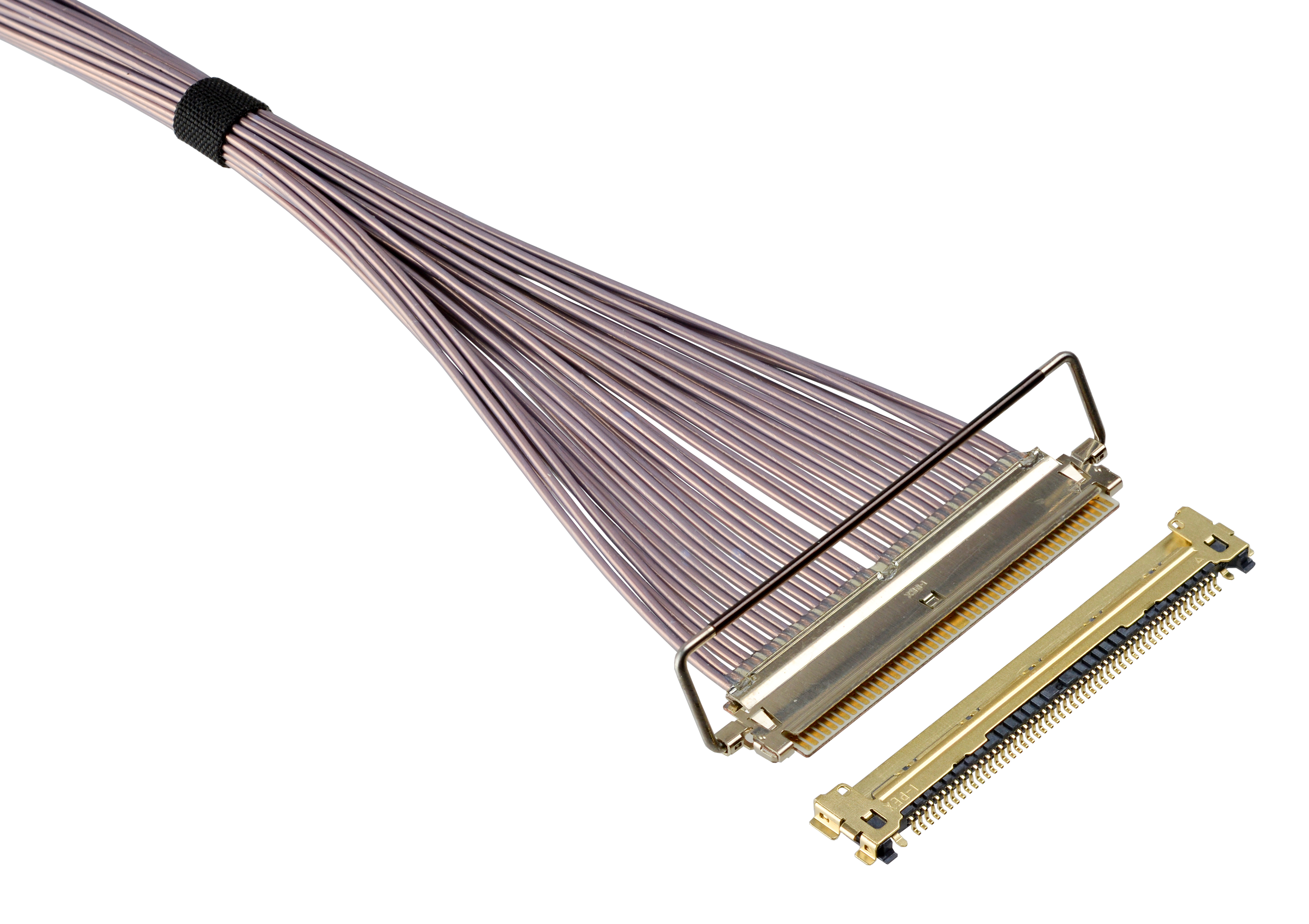
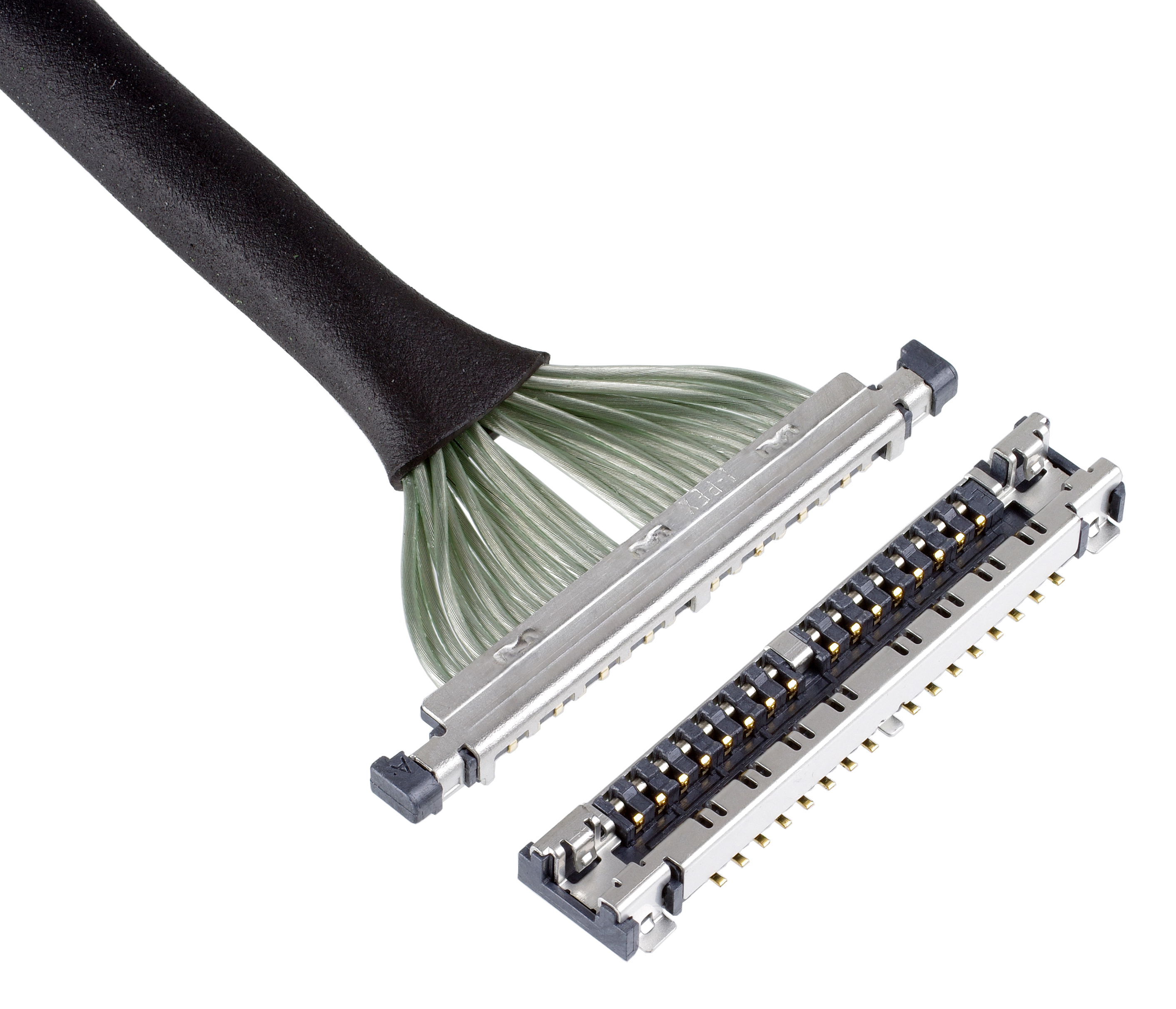
Number of channels in interface, required pin count, spacing between each pin, allowed mated width, length and profile height of plug and connector determine the type of connector that should be used. Maximum available area and location of connector on PCB also determines the mounting configuration for receptacle and plug harness assembly, which can be horizontal, right angle or vertical . I-PEX offers connectors in Horizontal, Right Angle and Vertical Mounting configurations and various different sizes and pin counts in its CABLINE® Series of High Speed Connectors.
|
Contact Pitch Options |
Mating Type Options |
|||||
|---|---|---|---|---|---|---|
 |
 |
 |
 |
 |
horizontal mating |
vertical mating |
0.5 mm pitch |
0.4 mm pitch |
0.35 mm pitch |
0.3 mm pitch |
0.25mm pitch |
 |
|
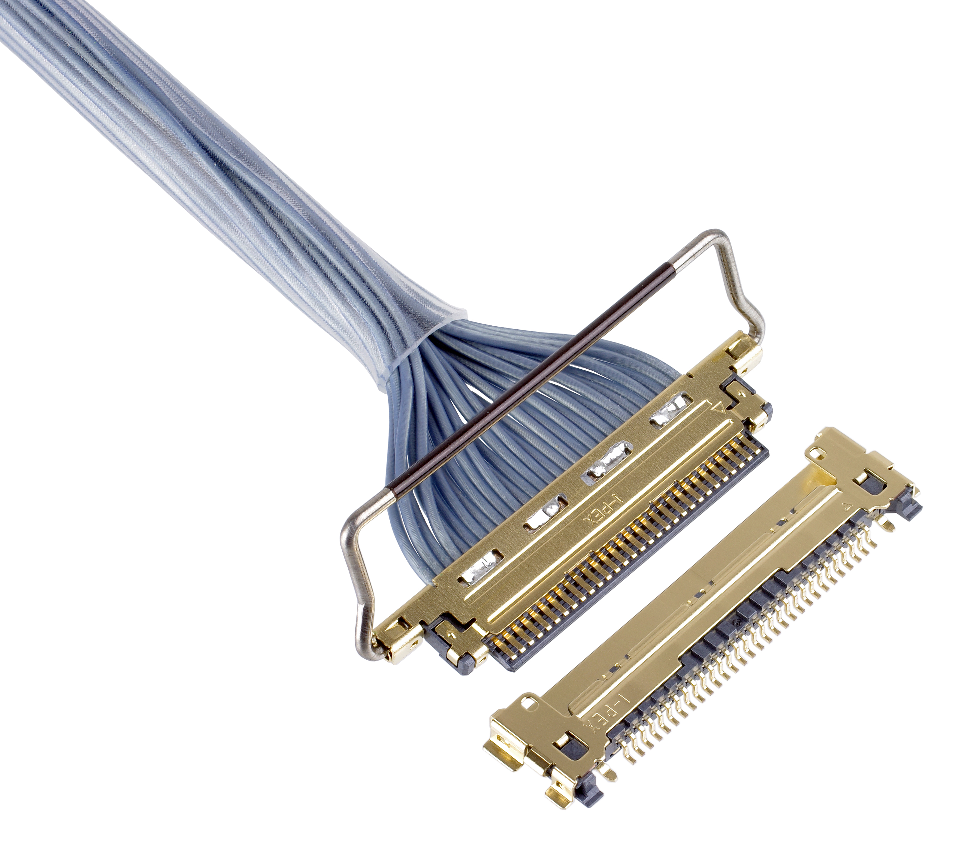
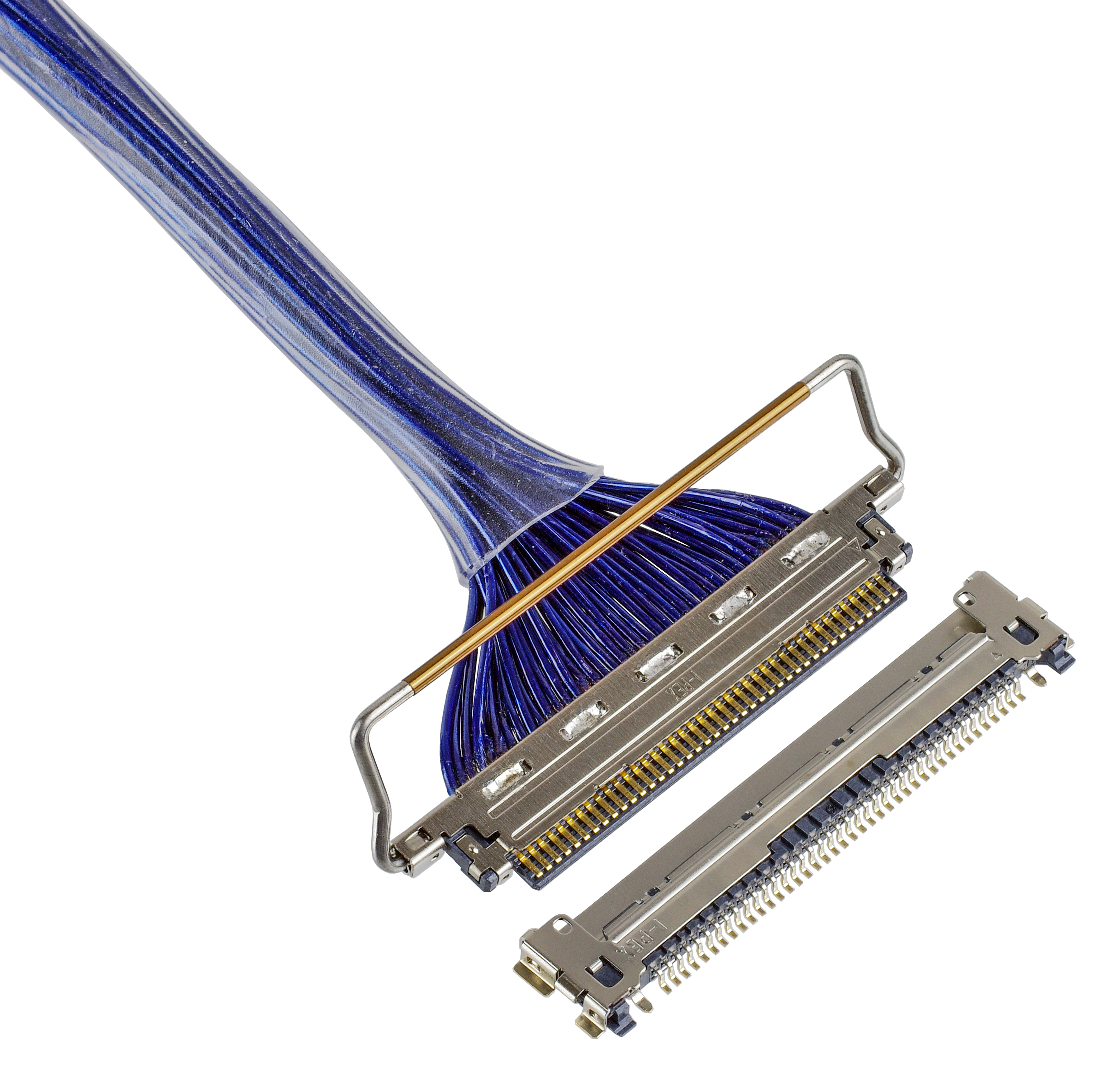
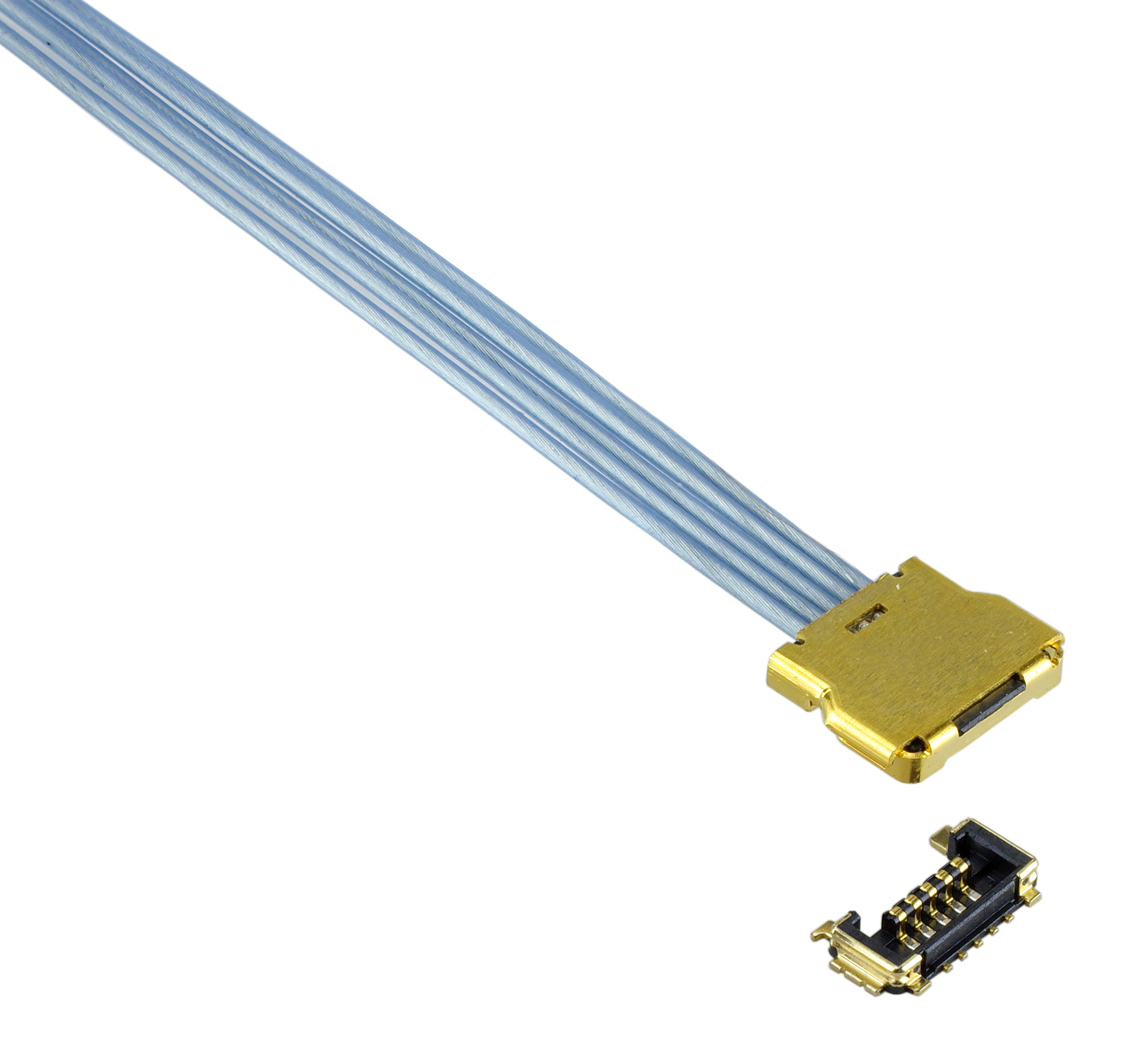
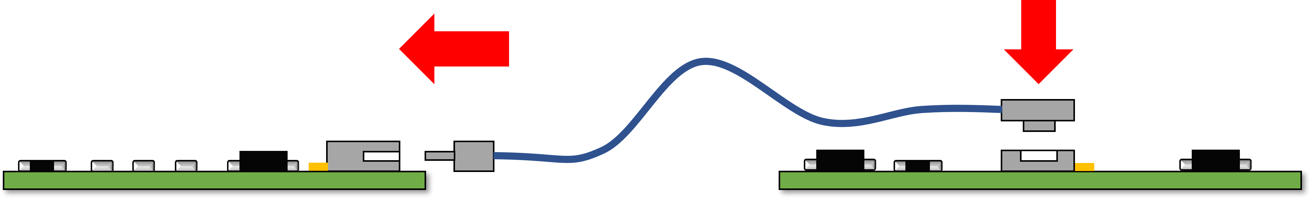
Vertical mount type connectors are mostly used in cable to board connectivity and can be placed anywhere on the PCB, typically close to IC pins. Vertical mount connectors are also available with guides design that are helpful in alignment of plug and receptacle for proper mating specially in board to board blind mating applications. Horizontal mount type connectors, on the other hand, are typically placed on edge of the board and generally need more clearance around the connector for proper matig of cable assembly to the connector on the baord. Horizontal mount connectors are more suitable for boards where the signal traces are routed all the way to the edge of board for IO connectivity to peripheral systems like camera, speaker, display or a test board etc. In general, the horizontal mount connectors can have lower profile height as compared to vertical mount connectors since the wipe contacts can be longer in X-axis direction as shown in the Figure 2 below.
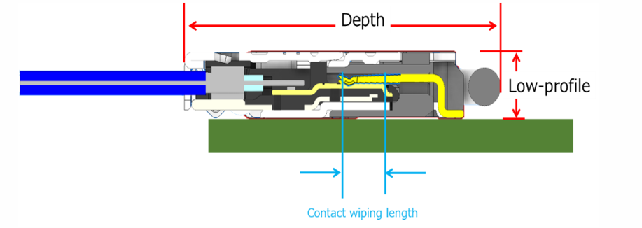
Contact wipe length also plays an important role in the connector retention force. There is a probability of losing contact in mated connection of low profile vertical mount connectors since the contact wiping length is small, specially in portable, handheld systems which are subject to falling and dropping down. Connectors with mechanical lock and coushioning material on the top help suppliment the mated retention force in such applications. More details about the mating configurations and rentention forces of connectors can be found at : Mating Direction of Connectors
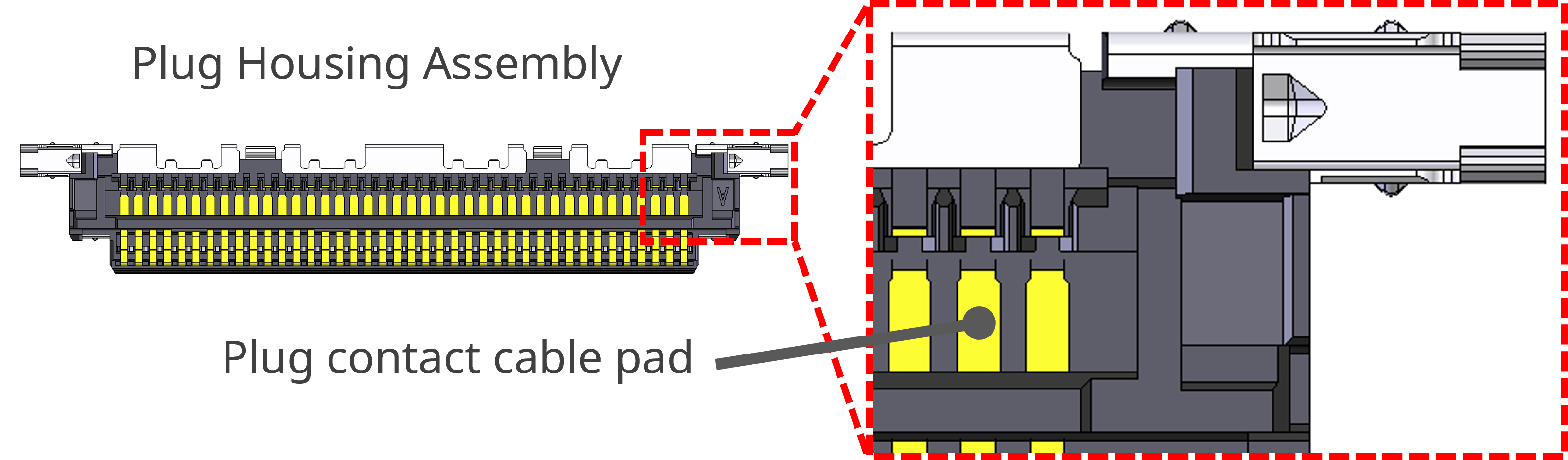
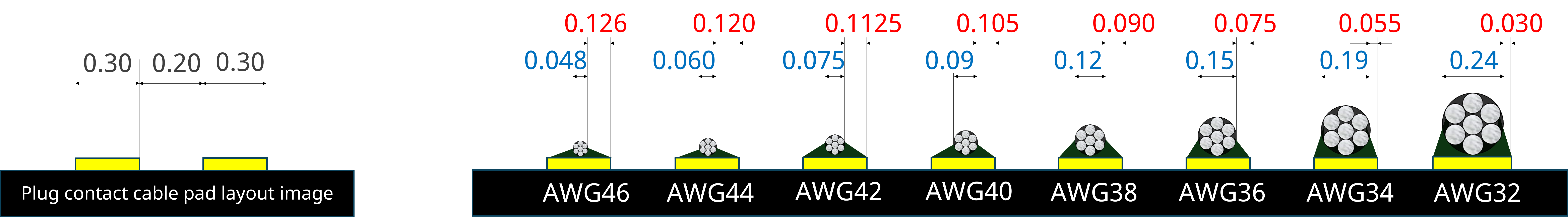
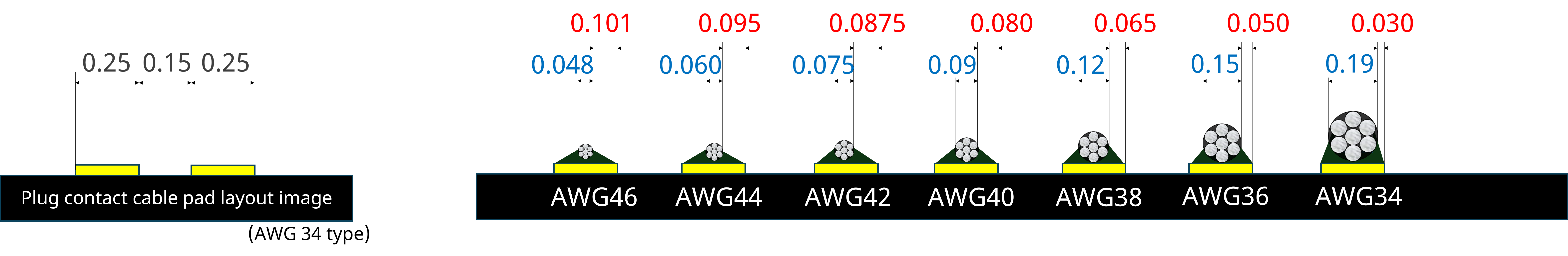
Connector pin pitch i.e. the spacing between pins of the connector also determines the size of the Micro-coaxial and Twinaxial cables that can be used in the Harness Assemblies. A cable with larger center conductor diameter results in lower Insertion Loss as compared to the cable with smaller center conductor diameter. A connector with tighter pin pitch i.e. pins closer to each other can accommodate thinner Micro-coaxial or Twinaxial cables which have higher attenuation as compared to the connectors with wider pin pitch i.e. pins spaced farther apart. Connectors with wider pin pitch can accommodate larger, thicker cables which end up resulting in lower Insertion Loss for the harness. Therefore, wider pin pitch helps in selecting the larger cable size and minimizing the loss in the application, while smaller pitch minimizes the board space required. A comparison of wire guages and pad sizes for both 0.5mm and 0.4mm pitch connectors is shown below for reference.
 |
 |
 |
 |
||
 |
||
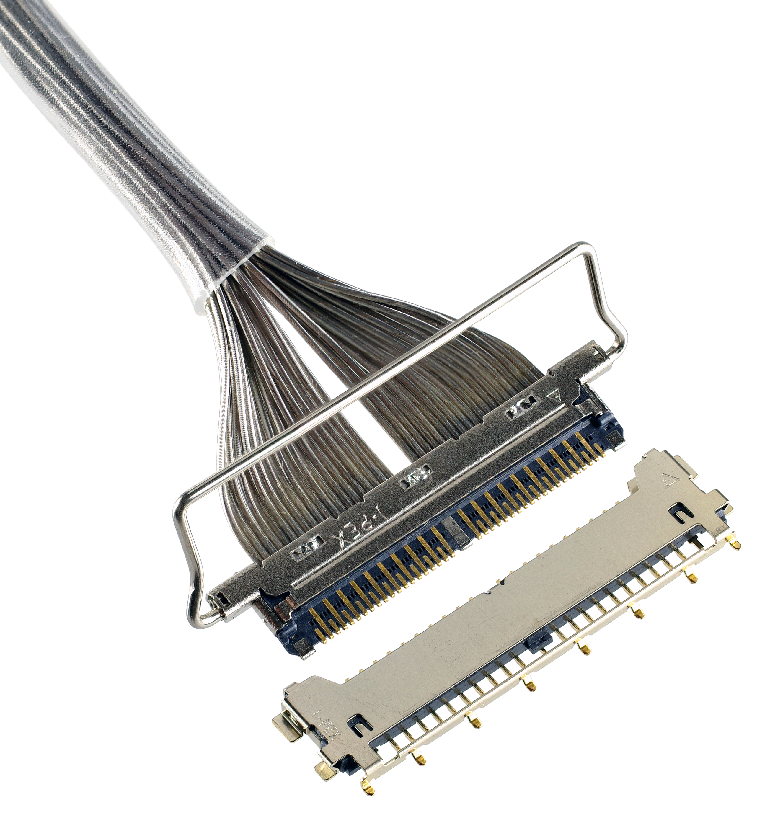
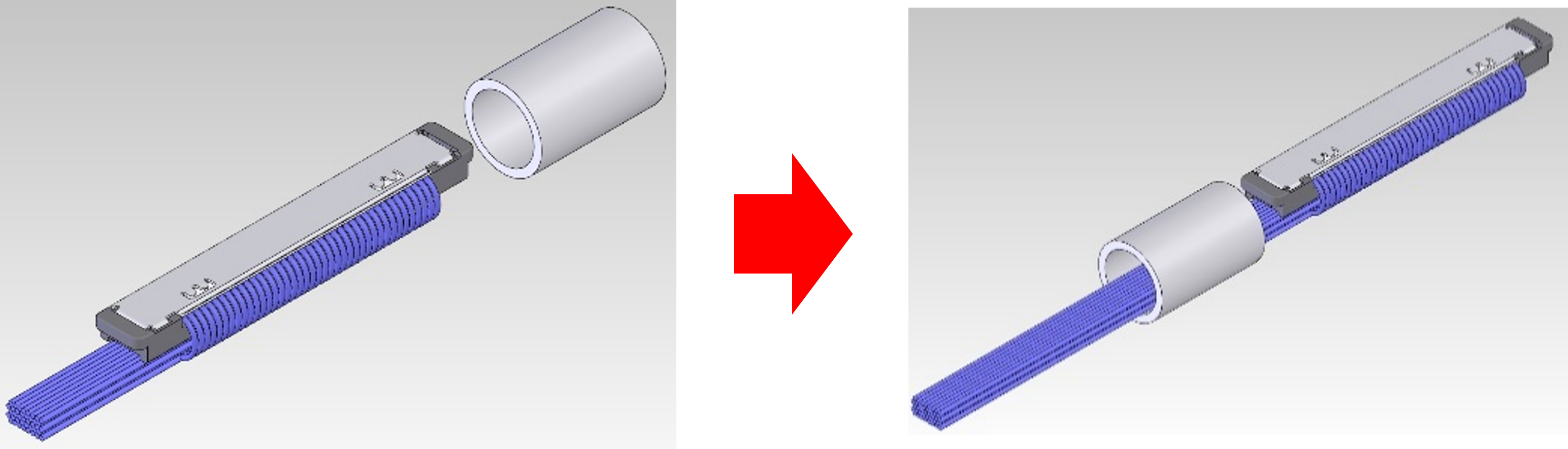
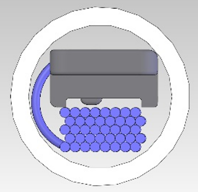
Smaller size and unique design of I-PEX connectors also enables fitting these connectors through much smaller spaces. These connectors can be threaded through hinged components in limited spaces with out damaging the connector or the cables as shown in the Figure below. High flexibility of Micro-coaxial cables coupled with minimal connector width allows passing the harness assemblies through the hinges in products like Laptop computers and cell phones with foldable screens, thereby increasing the number of times the screen can be folded and unfolded. For more details on how to use CABLINE harness assemblies in hinge component pass through applications, click on the link and image below.
Hinge Component Pass-Through with CABLINE® Harness Assemblies
 |
 |