アッセンブリのための利用可能な面積

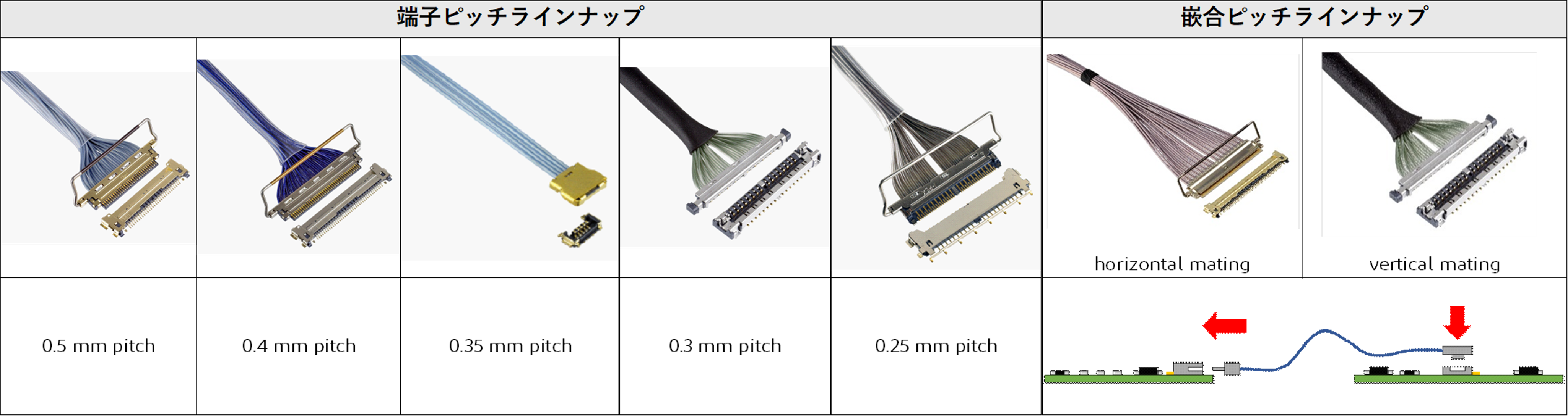
インターフェースのチャンネル数、必要なピン数、各ピンの間隔、プラグとコネクタの許容嵌合幅、長さ、プロファイルの高さによって、使用すべきコネクタのタイプが決まります。また、PCB上の最大利用可能面積とコネクタの位置により、リセプタクルとプラグのハーネスアッセンブリの取り付け形状が決まります。I-PEXは、CABLINE®高速コネクタシリーズで、水平、ライトアングル、垂直実装構成、さまざまなサイズとピン数のコネクタを提供しています。


Contact Pitch Options

Mating Type Options

CABLINE-VS CABLINE-CA CABLINE-UY CABLINE-UA II CABLINE-CX II without cover CABLINE-CAP
horizontal mating
CABLINE-UA II
vertical mating
0.5 mm pitch
0.4 mm pitch
0.35 mm pitch
0.3 mm pitch
0.25mm pitch
mating type options


垂直実装タイプのコネクタは、主にケーブルと基板の接続に使用され、PCB上の任意の場所、通常はICピンの近くに配置することができます。垂直実装コネクタは、特に基板対基板のブラインド嵌合アプリケーションにおいて、プラグとリセプタクルの適切な嵌合のための位置合わせに役立つガイド設計も利用可能です。一方、水平実装タイプのコネクタは、一般的に基板の端に配置され、基板上のコネクタにケーブルアッセンブリを適切に嵌合するために、コネクタの周囲にクリアランスが必要です。水平コネクタは、カメラ、スピーカー、ディスプレイ、テストボードなどの周辺システムへのIO接続のために、信号トレースが基板の端まで配線されている基板に適しています。一般的に水平コネクタは、下の図2に示すように、X軸方向に長い有効嵌合長を持つことができるため、垂直コネクタに比べてプロファイルの高さを低くすることができます。
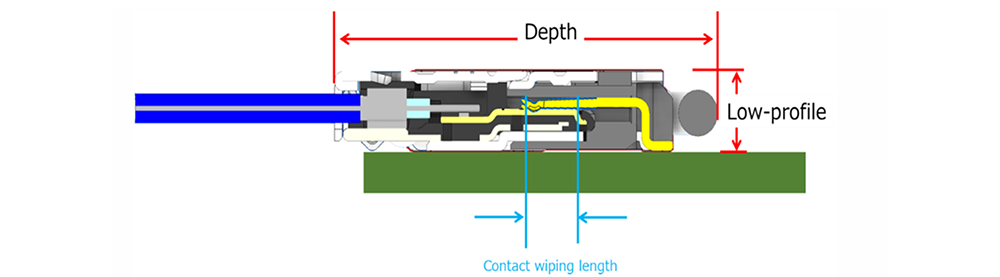
 

Real Estate_2
図2. 垂直コネクタの接触ワイピング長さ


有効嵌合長もコネクタ保持力に重要な役割を果たします。特に、携帯電話、タブレット、ゲーム機などと言ったハンドヘルド型のシステムでは、落下や転倒の可能性があるため、有効嵌合長が短く、低背の垂直マウントコネクタの嵌合接続では、接続が損なわれる可能性があります。このような用途では、上部にメカニカルロックとクッション材を備えたコネクタが嵌合保持力を補うのに役立ちます。コネクタの嵌合構成と保持力の詳細についてはこちらをご覧ください: I-PEX コネクタの嵌合方向


コネクタのピンピッチ、すなわちコネクタのピン間の間隔は、ハーネスアッセンブリに使用できる細線同軸ケーブルと Twinax ケーブルのサイズを決定します。中心導体径が大きいケーブルは、中心導体径が小さいケーブルに比べて挿入損失が小さくなります。ピンピッチの狭いコネクタは、ピンピッチの広いコネクタに比べ、減衰の大きい細線同軸ケーブルやTwinaxケーブルに対応できます。ピンピッチの広いコネクタはより太いケーブルに対応できるため、ハーネスの挿入損失が小さくなります。したがって、ピンピッチが広いほど、より太いケーブルサイズを選択し、アプリケーションでの損失を最小限に抑えることができます。参考までに、0.5mmピッチと0.4mmピッチのコネクタのワイヤゲージとパッドサイズの比較を以下に示しています。


Real Estate_3 Real Estate_4 Real Estate_5
Real Estate_6
Real Estate_7


I-PEXコネクタの小型化とユニークなデザインは、これらのコネクタをはるかに小さなスペースに通すことを可能にします。これらのコネクタは下図に示すように、コネクタやケーブルを損傷することなく、限られたスペースのヒンジ部品に通すことができます。細線同軸ケーブルの高い柔軟性と最小限のコネクタ幅により、ノートパソコンや携帯電話の折りたたみ式スクリーンのような製品のヒンジにハーネスを通すことができ、スクリーンの折りたたみと展開の回数を増やすことができます。CABLINEハーネスアッセンブリのヒンジ部用途アプリケーションでの使用方法の詳細については、以下のリンクと画像をクリックしてください。
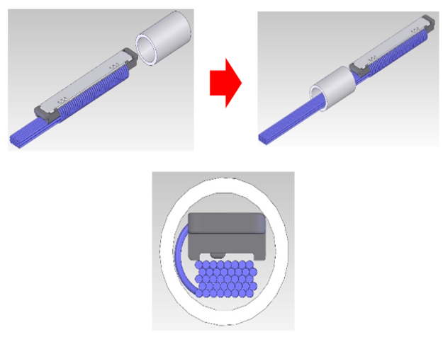
細線同軸コネクタハーネスによるヒンジ部通過シミュレーション


Real Estate_8
Real Estate_9


細線同軸・Twinaxial コネクタページに戻る

Real Estate_1

Vertical mount type connectors are mostly used in cable to board connectivity and can be placed anywhere on the PCB, typically close to IC pins. Vertical mount connectors are also available with guides design that are helpful in alignment of plug and receptacle for proper mating specially in board to board blind mating applications. Horizontal mount type connectors, on the other hand, are typically placed on edge of the board and generally need more clearance around the connector for proper matig of cable assembly to the connector on the baord. Horizontal mount connectors are more suitable for boards where the signal traces are routed all the way to the edge of board for IO connectivity to peripheral systems like camera, speaker, display or a test board etc. In general, the horizontal mount connectors can have lower profile height as compared to vertical mount connectors since the wipe contacts can be  longer in X-axis direction as shown in the Figure 2 below. 

Contact Wiping length in Horizontal mount connectors

Contact wipe length also plays an important role in the connector retention force. There is a probability of losing contact in mated connection of low profile vertical  mount connectors since the contact wiping length is small, specially in portable, handheld systems which are subject to falling and dropping down. Connectors with mechanical lock and coushioning material on the top help suppliment the mated retention force in such applications. More details about the mating configurations and rentention forces of connectors can be found at : 

Connector pin pitch i.e. the spacing between pins of the connector also determines the size of the Micro-coaxial and Twinaxial cables that can be used in the Harness Assemblies. A cable with larger center conductor diameter results in lower Insertion Loss as compared to the cable with smaller center conductor diameter. A connector with tighter pin pitch i.e. pins closer to each other can accommodate thinner Micro-coaxial or Twinaxial cables which have higher attenuation as compared to the connectors with wider pin pitch i.e. pins spaced farther apart. Connectors with wider pin pitch can accommodate larger, thicker cables which end up resulting in lower Insertion Loss for the harness. Therefore, wider pin pitch helps in selecting the larger cable size and minimizing the loss in the application, while smaller pitch minimizes the board space required. A comparison of wire guages and pad sizes for both 0.5mm and 0.4mm pitch connectors is shown below for reference.

Real Estate_3

Smaller size and unique design of I-PEX connectors also enables fitting these connectors through much smaller spaces. These connectors can be threaded through hinged components in limited spaces with out damaging the connector or the cables as shown in the Figure below. High flexibility of Micro-coaxial cables coupled with minimal connector width allows passing the harness assemblies through the hinges in products like Laptop computers and cell phones with foldable screens, thereby increasing the number of times the screen can be folded and unfolded. For more details on how to use CABLINE harness assemblies in hinge component pass through applications, click on the link and image below. 

Real Estate_4

Contents