ハーネスアッセンブリのピン配列

Depending on the signal pin out, lay out and routing of board traces, the pin assignments can be different on each connector in the harness assembly. Two different types of pin out configurations are offered in I-PEX High Speed Harness Assemblies i.e. 1-N type straight pin out and 1-1 type mirror pin out configurations for routing and placement flexibility in designs. 

For example pin 1 on connector at one end of harness is connected to pin N of the connector on the other side of harness. In such a configuration, each micro-coaxial cable is kept straight while  connecting the two pins on on each side to avoid any crossing of cables with each other in the harness assembly. This placement is ahieved by rotating the PCB/ connector lead frame by 180 degrees relative to the other side in the harness. 1-N configuration of Harness Assemblies is useful in board designs where two components with Mirror Pin Out relative to each other must be connected in either a board to board or chip to chip on the same board design as shown below, without ruting the signals on various different layers or by using multiple Vias to cross the signals.

1 - N Pin Out of Micro-coaxial Harness Assemblies
  Connector 1 Connector 2
Pin Assignment N 1
N-1 2
2 N-1
1 N


However, in 1-1 pin out configuration, pin 1 on connector at one end of harness is connected to pin 1 of the connector on the other side of harness. 1-1 configuration of Harness Assemblies is useful in board designs where two components either on the same board or on different boards with the same Pin Out relative to each other must be connected. A 1-1 pin out harness assembly is shown in the Figure 2 below:

1 - 1 Pin Out of Micro-coaxial Harness Assemblies
  Connector 1 Connector 2
Pin Assignment N N
N-1 N-1
2 2
1 1

Contents

信号のピンアウト、レイアウト、基板トレースの配線により、ハーネスアッセンブリの各コネクタでピン配置が異なる場合があります。I-PEX高速ハーネスのアッセンブリには、配線や配置の柔軟性を考慮し、1-Nタイプのストレートピン配置と1-1タイプのミラー配置のピンの2種類のピンアウト構成があります。

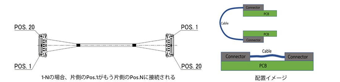
例えば、ハーネスの一端にあるコネクタの1番ピンは、ハーネスの反対側にあるコネクタのN番ピンに接続されています。このような構成では、各細線同軸ケーブルは、ハーネス・アセンブリ内でケーブル同士が交差するのを避けるため、両側の2つのピンを接続しながらまっすぐに保たれます。この配置は、PCB/コネクタのリードフレームをハーネスの反対側に対して180度回転させることで実現されます。ハーネスアッセンブリの1-N形状は、下図に示すように、互いにミラー配置のピンを持つ2つのコンポーネントを、同じ基板設計上の基板対基板またはチップ対チップのいずれかで接続する必要がある基板設計において、さまざまな異なる層で信号を交差させたり、複数のバイアスを使用して信号を交差させたりすることなく有効です。

1-Nの場合、片側のPos.1がもう片側のPos.Nに接続される。


Pin Out_1
図1. 細線同軸ハーネスアッセンブリの1-Nピン配置


Pin Out_2

Pin Out_3


  Connector 1 Connector 2
Pin Assignment N 1
N-1 2
2 N-1
1 N

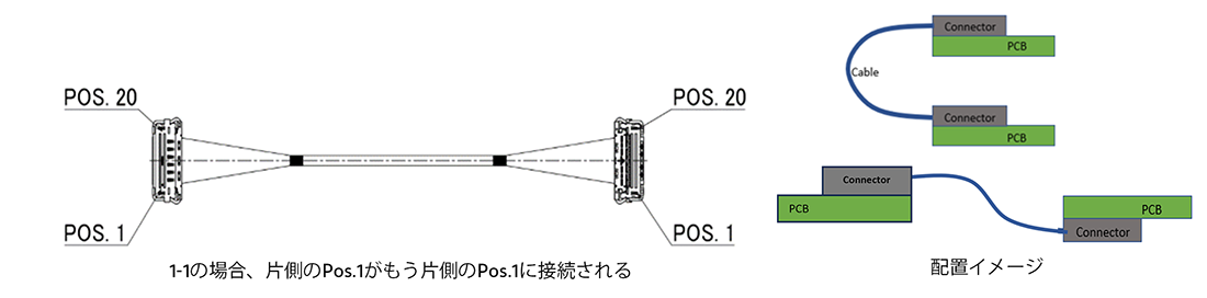
ただし、1-1ピン配置構成では、ハーネスの片端にあるコネクタのピン1が、ハーネスの反対側にあるコネクタのピン1に接続されます。ハーネスアッセンブリの1-1構成は、同一基板上または異なる基板上で互いに同じピン配置を持つ2つのコンポーネントを接続する必要がある基板設計に役立ちます。1-1ピン配置のハーネスアッセンブリを図2に示します。


1-1の場合、片側のPos.1がもう片側のPos.1に接続される。


Pin Out_4
図2. 細線同軸ハーネスアッセンブリの1-1ピン配置

Pin Out_5

Pin Out_6

                                  配置イメージ


  Connector 1 Connector 2
Pin Assignment N N
N-1 N-1
2 2
1 1


Micro-Coaxial・Twinaxialコネクタページに戻る