

High Design Flexibility
I-PEX provides a diverse range of cable diameter options designed to meet specific requirements for insertion loss and minimum bend radius. This variety ensures flexibility in designing connectivity within wireless devices. Depending on the type of MHF® connector, the outer diameters of coaxial cables vary from 0.48 mm (MHF® 5) to 3.0 mm (MHF®-TI).
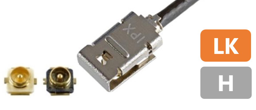
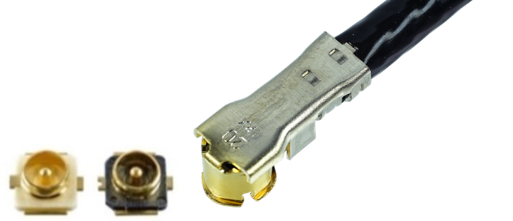
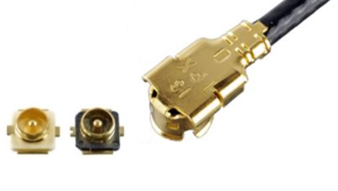
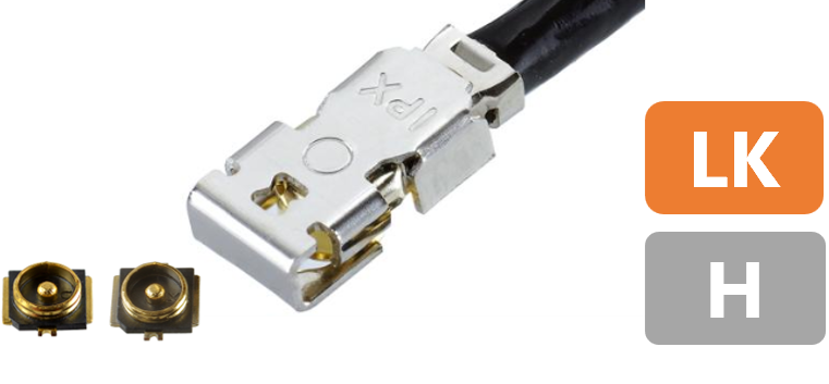
Product Name |
MHF® I LK |
MHF® I |
MHF® 4L LK |
MHF® 4L |
MHF® 4 | ||||
Appearance |
|
|
|
|
|
|
|
|
|
Feature |
MHF® I with Mechanical lock |
Low Insertion Loss |
Industry standard Most cable options |
MHF® 4L with Mechanical lock |
Low Insertion Loss and VSWR |
Industry Standard for M.2 |
Industry Standard for M.2 |
Low profile 1.2 mm |
|
Part Number |
Plug |
20278-112R-** 20351-112R-37
|
20767-001R-20 |
20278-112R-** 20351-112R-37 (O.D. 1.37 mm) |
20632-001R-37 |
20632-001R-37 |
20565-001R-13 |
20572-001R-08 |
20611-001R |
Receptacle |
20279-001E-03 (3 pads) / 20441-001E-01 (4 pads) |
20449-001E-03 (MHF®4) / 20579-001E (MHF®4L) |
|||||||
Mated Height |
2.9 mm max. |
3.0 mm max. |
2.5 mm max. |
2.0 mm max. |
1.7 mm max. |
1.4 mm max. |
1.2 mm max. |
1.2 mm max. |
|
SMT Size |
3.1 x 3.0 mm |
3.1 x 3.0 mm |
3.1 x 3.0 mm |
2.0 x 2.0 mm |
2.0 x 2.0 mm |
2.0 x 2.0 mm |
2.0 x 2.0 mm |
2.0 x 2.0 mm |
|
Cable Size
|
3.0
|
- |
- |
- |
- |
- |
- |
- |
- |
2.8
|
- |
- |
- |
- |
- |
- |
- |
- |
|
2.0
|
- |
AWG 26 |
- |
- |
- |
- |
- |
- |
|
1.8
|
AWG 30 |
- |
AWG 30 |
- |
- |
- |
- |
- |
|
1.37 mm |
AWG 30 |
- |
AWG 30 |
AWG 30 |
AWG 30 |
- |
- |
- |
|
1.32 mm |
AWG 32 |
- |
AWG 32 |
- |
- |
- |
- |
- |
|
1.13 mm |
AWG 32 |
- |
AWG 32 |
- |
- |
AWG 32 |
- |
- |
|
0.95 mm |
- |
- |
- |
- |
- |
AWG 33 |
- |
- |
|
0.81 mm |
AWG 36 |
- |
AWG 36 |
- |
- |
- |
AWG 36 |
AWG 36 |
|
0.64 mm |
- |
- |
- |
- |
- |
- |
AWG 36 |
- |
|
0.48 mm |
- |
- |
- |
- |
- |
- |
- |
- |
|
Frequency Range |
Up to 9 GHz |
Up to 9 GHz |
Up to 9 GHz |
Up to12 GHz
|
Up to12 GHz (MHF® 4L receptacle)
|
Up to12 GHz (MHF® 4L receptacle)
|
Up to12 GHz (MHF® 4L receptacle) Up to9 GHz (MHF® 4 receptacle) |
Up to 9 GHz |
|
VSWR
|
DC to 3 GHz |
1.3 max. |
1.3 max. |
1.3 max. |
1.3 max. |
1.3 max. |
1.3 max. |
1.3 max. |
1.3 max. |
3 to 6 GHz |
1.5 max. |
1.5 max. |
1.5 max. |
1.4 max. |
1.4 max. |
1.45 max. |
1.45 max. |
1.5 max. |
|
6 to 9 GHz |
1.6 max.
|
1.6 max. |
1.6 max. (O.D.1.32 mm) 1.9 max. (O.D.0.81, 1.13, 1.37, 1.8 mm) |
1.5 max. |
1.5 max. |
1.6 max. |
1.6 max. |
2.0 max. |
|
9 to 12 GHz |
- |
- |
- |
1.6 max. |
1.6 max. |
1.9 max. |
1.9 max. |
- |
|
Operating Temperature |
-40 to 90℃
|
-40 to 90℃ (233 to 363 K) |
-40 to 90℃
|
-40 to 90℃ (233 to 363 K) |
-40 to 90℃ (233 to 363 K) |
-40 to 90℃ (233 to 363 K) |
-40 to 90℃
|
-40 to 90℃ (233 to 363 K) |
|
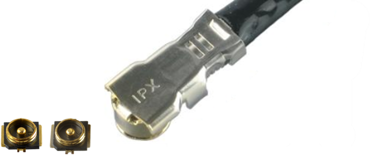
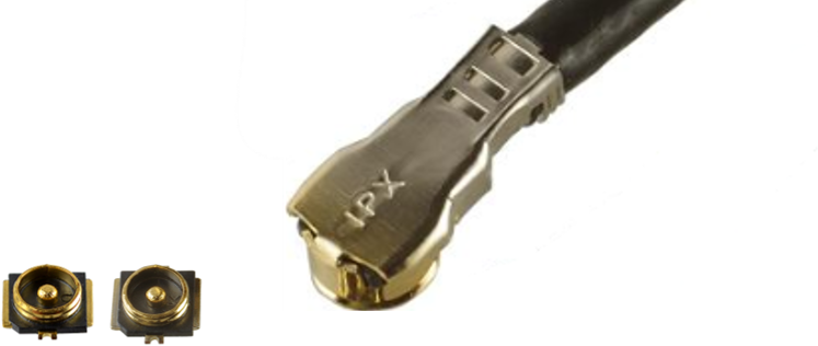
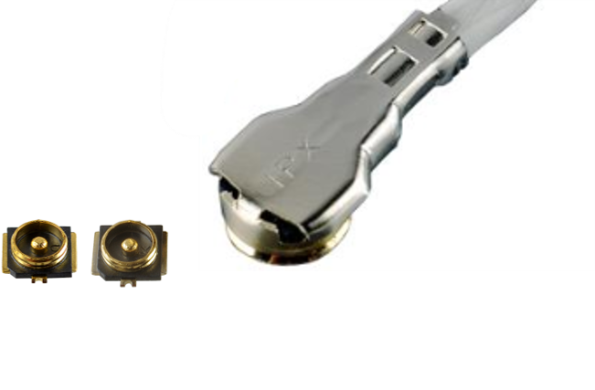
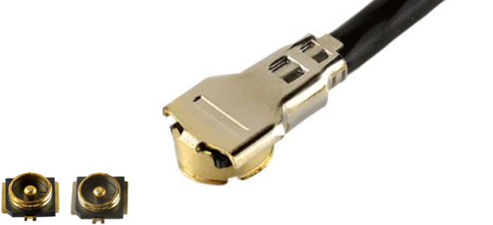
(*) Please contact us for higher temperature connectors.
Product Name |
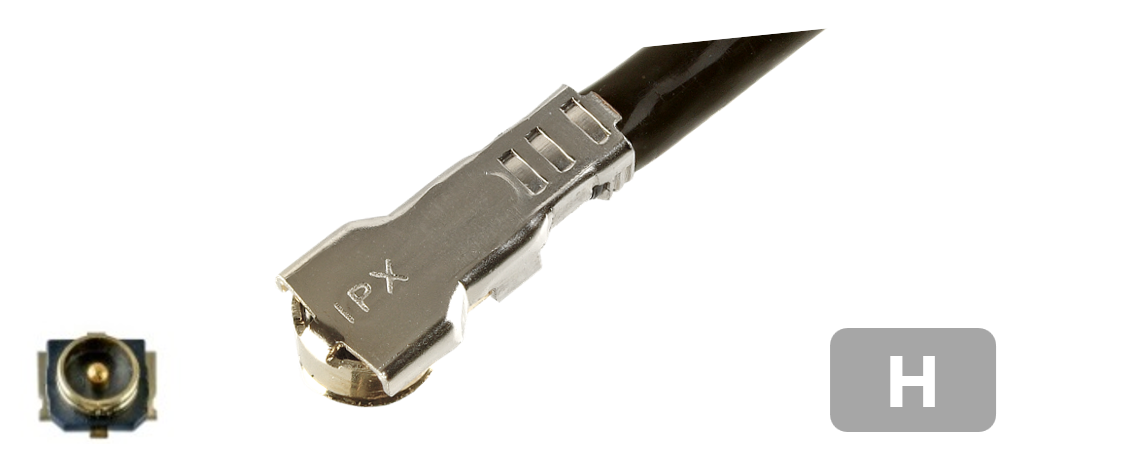
MHF® 5L |
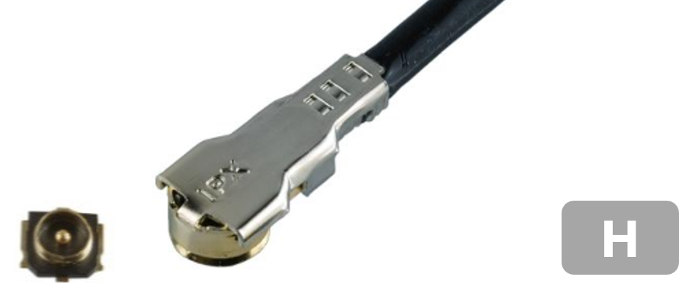
MHF® 5 |
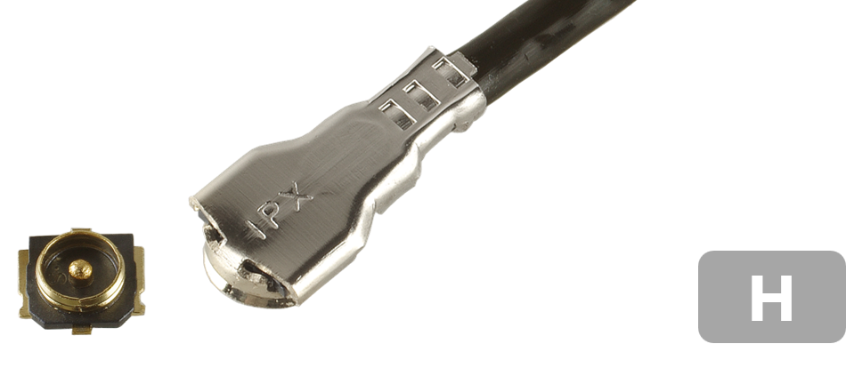
MHF® 7S |
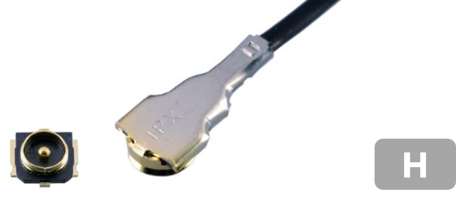
MHF®-TI | MHF®-SW23 plug | |||
Appearance |
 |
 |
 |
 |
|
|
|
|
Feature |
Low insertion Loss and VSWR through 15 GHz |
Low Insertion Loss and VSWR through 15 GHz |
Low profile 1.0 mm |
Low profile 1.0 mm |
Excellent EMC performance with fully-shielded design |
Robust design for automotive telematics antenna and camera sensors |
Mating with switch connector (20549-001E) |
|
Part Number |
Plug |
20668-001R-13 |
20714-001R-81 |
20711-001R-81 |
20615-002R-48 |
20980-001R-13 |
20859-001R-01 |
20851-001R |
Receptacle |
20566-001E-01 |
20566-001E-01 |
20566-001E-01 |
20566-001E-01 |
20981-001E-02 |
20860-001E-01 |
- |
|
Mated Height |
1.3 mm max. |
1.3 mm max. |
1.0 mm max. |
1.0 mm max. |
1.4 mm max. |
3.65 mm max. |
3.7 mm max. |
|
SMT Size |
2.0 x 2.0 mm |
2.0 x 2.0 mm |
2.0 x 2.0 mm |
2.0 x 2.0 mm |
2.0 x 2.0 mm |
9.4 x 5.18 mm |
2.3 x 2.3 mm |
|
Cable Size
|
3.0
|
- |
- |
- |
- |
- |
- |
- |
2.8
|
- |
- |
- |
- |
- |
- |
- |
|
2.0
|
- |
- |
- |
- |
- |
- |
- |
|
1.8
|
- |
- |
- |
- |
- |
- |
- |
|
1.37 mm |
- |
- |
- |
- |
- |
- |
- |
|
1.32 mm |
|
- |
- |
- |
- |
- |
- |
|
1.13 mm |
AWG 32 |
- |
- |
- |
AWG 32 |
- |
AWG 32 |
|
0.95 mm |
- |
- |
- |
- |
- |
- |
- |
|
0.84 mm |
- |
AWG 33 |
- |
- |
- |
- |
- |
|
0.81
|
- |
- |
AWG 36 |
- |
- |
- |
- |
|
0.64 mm |
- |
- |
AWG 36 |
- |
- |
- |
- |
|
0.48 mm |
- |
- |
- |
AWG 38 |
- |
- |
- |
|
Frequency Range |
Up to 15 GHz |
Up to 15 GHz |
Up to 12 GHz |
Up to 12 GHz |
Up to 15 GHz |
Up to 6 GHz |
Up to 9 GHz |
|
VSWR
|
DC to 3 GHz |
1.3 max. |
1.3 max. |
1.3 max. |
1.3 max. |
1.3 max. |
1.5 max. |
- |
0.3 to 3 GHz |
- | - | - | - | - | - |
1.4 max. |
|
3 to 6 GHz |
1.4 max. |
1.4 max. |
1.5 max. |
1.5 max. |
1.35 max. |
1.5 max. |
1.6 max. |
|
6 to 9 GHz |
1.5 max. |
1.5 max. |
1.6 max. |
1.6 max. |
1.4 max. |
- |
2.0 max. |
|
9 to 12 GHz |
1.5 max. |
1.5 max. |
1.8 max.
|
1.6 max. |
1.45 max. |
- |
- |
|
12 to 15 GHz |
1.6 max. |
1.6 max. |
- |
- |
1.5 max. |
- |
- |
|
Operating Temperature |
-40 to 90℃
|
-40 to 90℃
|
-40 to 90℃
|
-40 to 90℃
|
-40 to 90℃
|
-40 to 105℃
|
-40 to 85℃
|
|
Automotive Standards |
- |
- |
- |
- |
- |
USCAR-2 * |
- |
|
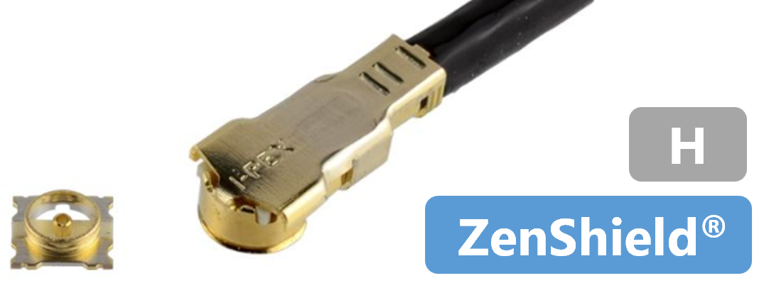
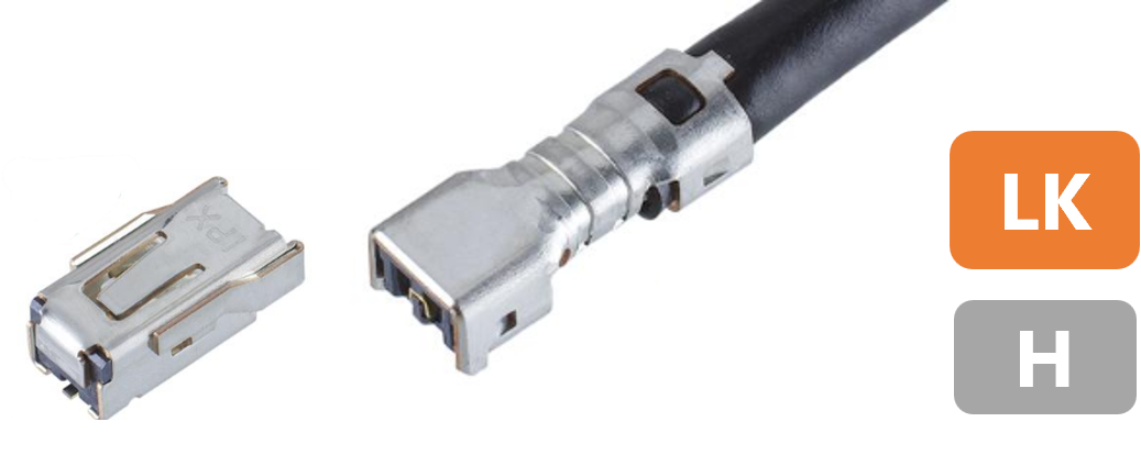
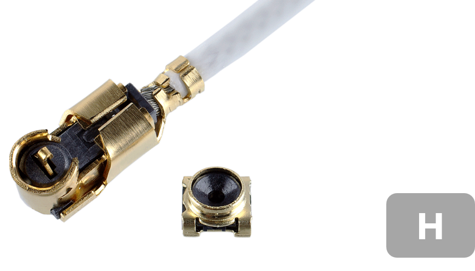
(*) Rev.6 - 5.4.6 (Vibration), 5.6.1 (Thermal Shock), 5.6.2 (Temp. & Humidity Cycle), 5.6.3 (High Temp. Exposure & Life) evaluation passed.
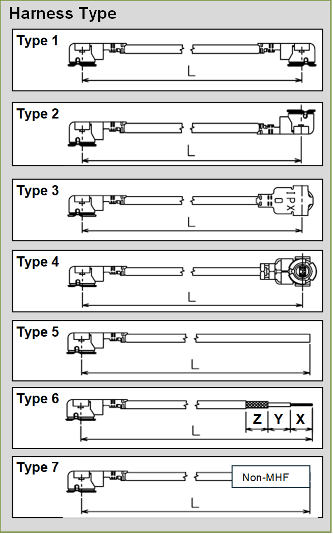
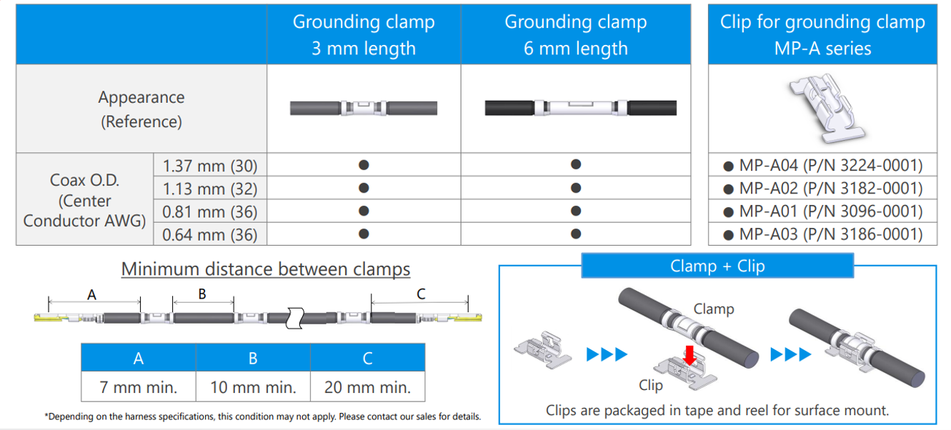
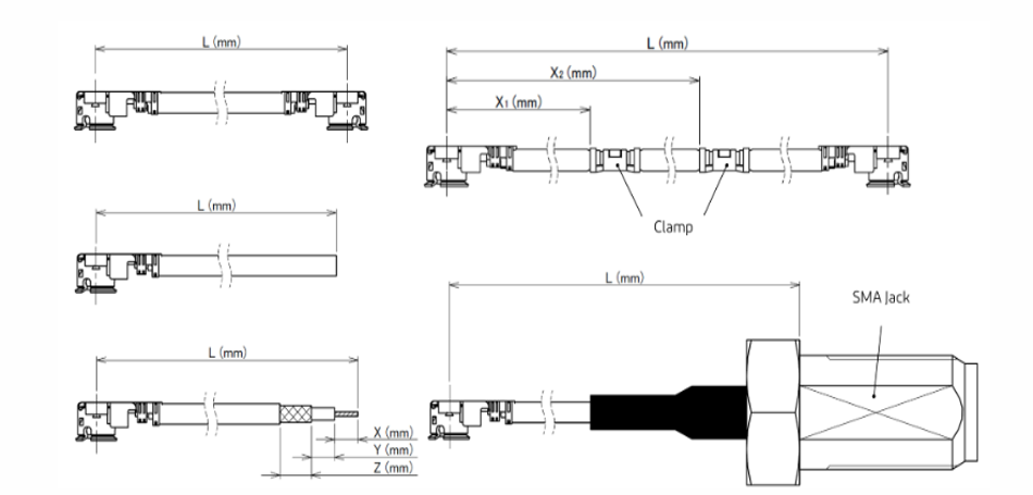
I-PEX sells completed MHF® harnesses in multiple configurations MHF-to-MHF, blunt cut, strip and tinned. Other value-added options include orientation in 90-degree increments, jacket cut-outs or windows for grounding, adding MP-A clamps. If custom configurations are required, please contact us through the inquiry form and provide your desired cable length, connector type, and cable diameter.
 |
 |
Features and Benefits of I-PEX RF Solutions
- 1. Compact Size and High Density
- 2. High Frequency and Data Rates
- 3. Superior EMC Performance
- 4. High Design Flexibility
- 5. Robust Design with Integrated Locking Features
- 6. Key Industry Standards
- 7. Consistent Performance with i-Fit® Technology
- 8. MHF® Switch Products for Antenna Testing
- 9. Available Accessories
- 10. PCB Stack Up Optimization Services
- 11. Signal Integrity Data
- 12. Signal Integrity Testing


