极细同轴线/Twinaxial连接器

I-PEX is the pioneer of micro-coaxial connectors and mass produced the first CABLINE® micro-coaxial connector in 1996. As the data rates and operating frequencies increase, I-PEX micro-coaxial / twinaxial connectors also evolved to meet this demand. This page is based on frequently asked questions about micro-coaxial / twinaxial connector, cable and cable assemblies and addresses the needs of both new and expert engineers, considering to use these products either for the first time or use them often in their designs.

Contents

1) What is a Micro-coaxial Cable Harness and why do you need it?

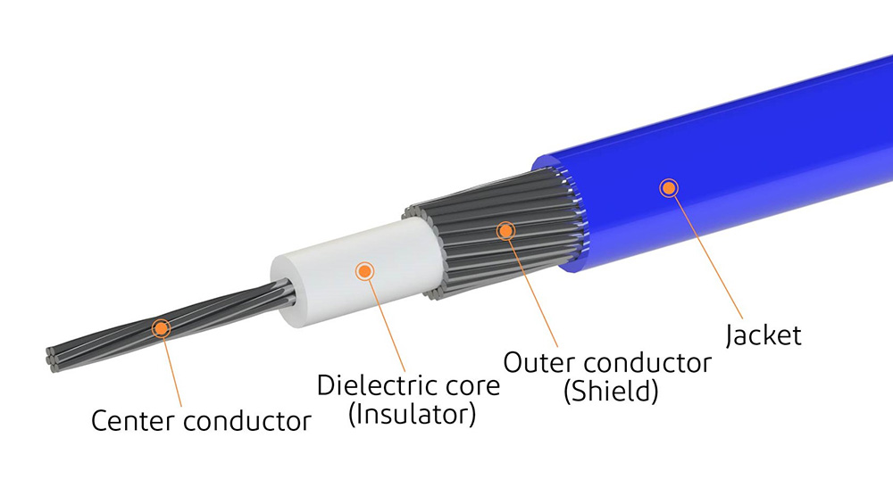
High frequency signals are more sensitive to electromagnetic radiation from near by communication sources like antennas, high speed board traces and transcievers on PCBs. By using Micro-coaxial cables, these high speed signals are well shielded from noise and signal integrity of data is preserved. A micro-coaxial cable includes a center conductor for signal transmission that is surrounded  by dielectric core for insulation. There is outer metallic jacket with multiple strands for ground return current followed by PVC type jacket for additional insulation. I-PEX offers complete micro-coaxial cable harness solutions for high frequency signals by using its fully shielded connectors with optional mechanical locking feature for reliable connect by a dielectric.

Coaxial Cable Structure

2) What is a Twinaxial Cable Harness and why do you need it?

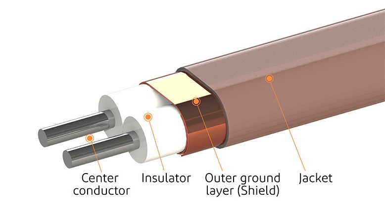
Twinaxial cables are more suitable for high speed digital data transmission that uses low voltage, low skew and tightly phase matched signals. These cables also dissipate less heat and offer smaller signal losses than PCB traces, so they can be used to interconnect the devices on the board. A Twinaxial cable has two center conductors typically used for differential signals. The two conductors are separated and surrounded by insualator like rubber or plastic. There is a outer layer of dielectric around these conductors for insulation just like in Micro-coaxial cables. There is a metallic outer conducting shield for ground return current and outer PVC type jacket. I-PEX offers complete Twinaxial Cable Harness solutions for high speed differential signals by using its fully shielded connectors with optional mechanical locking feature for reliable connectivity.

CABLINE series

3) What is the maximum operating frequency in your application?

Maximum operating frequency determines how fast and how much of the data can be transmitted in a high speed interface of communication system. Impedance mismatch and high Insertion Losses of interconnect medium in high speed digital data transmission result in closed signal eye, leading to high Bit Error Rate and data loss on receiving end. For this reason, it becomes even more important to use a high performance, low loss cable interconnect with well matched impedance so that the high speed signals can be transmitted with high fidelity. CABLINE® series of products offer low losses and can operate up to maximum frequency of 16GHz and data rates can be supported up to 64Gbps using PAM4 signalling. USB, eDP, Display Port and PCIe are some of the commonly supported proctocols.

Maximum Operating Frequency

4) What is the available real estate for connector/ receptacle and plug assembly?

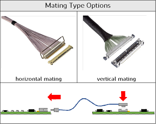
Number of channels in interface, required pin count, spacing between each pin, allowed mated width, length and profile height of plug and connector determine the type of suitable connector that should be used. Maximum available area and location of connector on PCB also determine the mounting configuration for receptacle and plug harness assembly, which can be horizontal or vertical . I-PEX offers connectors in both Horizontal and Vertical Mounting configurations and various different sizes and pin counts in its CABLINE® series of high speed connectors.

Real Estate

5) Is there a need to shield the high frequency or power signals in the harness?

Sometimes there is a need to transmit power, low speed control and high speed data signals all in the same harness. Due to the close proximity of surface mounted components or noise present in the system, the signals need to be shielded from EMI and cross talk. I-PEX offers full 360 degrees EMI shielding solution, called ZenShield® on its plugs for both Flexible Printed Circuit Cable, Micro-coaxial cables, and Twinaxial in CABLINE®  series products to cover both the signal contacts and the soldered tails of mated connector from EMI noise.

ZenShield® is offered in CABLINE® -VS II, CABLINE® -VS IIF, CABLINE®-CA II, CABLINE®-CA II PLUS, CABLINE®-CA IIP PLUS, CABLINE®-CA IIF, CABLINE®-CX II and CABLINE®-UM series products.

Graphic Connector With Integrated Shielding for Tail Pins

6) What are the main losses in high speed cable assemblies? How can the losses be minimized in my Harness Assemblies?

Insertion Loss, Return Loss and VSWR are key performance indicators of High Speed Twinaxial and Micro-Coaxial Cable Assemblies. A high performance Micro-coaxial cable results in excellent signal integrity  and reduced losses in high speed applications. At I-PEX we take pride to offer the high performance CABLINE® Micro-coaxial and Twinaxial Cable Assemblies which are built by using automated assembly processes to ensure consistent high quality and low losses in every finished product.

micro-coaxial cable

7) What are the bend, flex and twist requirements of the harness?

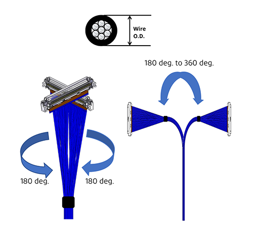
Both Micro-coaxial and Twinaxial cables are specified for Minimum Bend Radius, a parameter that determines how tightly these cables can be bent repeatedly with out being damaged and still ensuring high signal integrity. Minimum bend radius is typically measured in millimeters. Micro-coaxial cables are also specified for twisting, a parameter that allows the rotational movement of cable along the Y axis and is typically measured in degrees.  When it comes to Micro-coaxial cables, the recommended minimum bending radius of cable is “6 times Wire O.D" but the actual specification depends on customer's selected coaxial cable.

 Bend Flex and Twist Requirements_1

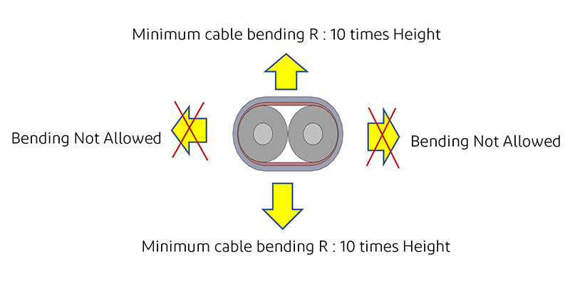
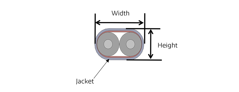
For Twinaxial Cables, the construction of cable restricts the bending and flexing in the direction of its height only as shown below. As a rule of thumb, the Minimum Bend radius for Twinaxial cables is specified as 10 times the height of cable. Bending and flexing side ways, along Y-axis is not allowed.

 Bend Flex and Twist Requirements_2

8) What is the required pin out of harness assemblies?

Depending on the signal pin out, lay out and routing of board traces, the pin assignments can be different on each connector in the harness assembly. Two different types of pin out configurations are offered in I-PEX high speed harness assemblies i.e. 1-N type straight pin out and 1-1 type mirror pin out configurations for routing and placement flexibility in designs. 

Pin Out

9) What is the required jacketing and bundling type on harness?

Four different types of outer tapes or jackets are offered for high speed cable harnesses for increased routing and placement flexibility in designs.  The bundling tapes can be wrapped around the cables at multiple points covering some, most or all of the cabling area of the harness. Also, there is flat bundle type option for space constrained systems that need light weight, transparent outer jacket with fast heat dissipation and uniform stress distribution. 

Styles of Taping and Bundling In Micro-Coaxial Cable Harnesses

10) What are the typical high speed protocols supported by these harnesses?

USB 3, USB 4, Thunderbolt, Displayport, eDP, HDMI, MIPI and PCIe Gen 5 and Gen 6 are some of the commenly supported protocols with the maximum data rate of 64Gbps/Lane using PAM4 signal type.

I-PEX offers a tool which can be used to find the available connector options that are suitable for a specific industry standard such as MIPI, PCIe, USB etc. At the same time, it allows the users to see what types of industry standards are supported by each of I-PEX high speed connector family. 

Signal  Integrity Reference Tool

11) How is a Micro-coaxial Cable Harness prepared and how many types of cables can be supported?

Main Process of Plug Harness Preparation is as follows:

  1. 1.Strip and prepare cable sub-assembly
  2. 2.Set the Cable Sub-Assembly to the Plug Housing Assembly part and solder the exposed conductor to the plug signal terminal
  3. 3.Set Lock Bar Assembly (or Lock Bar) to Plug Housing Assembly parts
  4. 4.Cover the plug shell and solder the required area to complete the plug harness
Image of plug harness assembly process
 

I-PEX极细同轴线连接器是显示器,摄像模组,储存设备和其他应用的理想选择。

Table of contents :


What is a coaxial cable?

The basic structure of the cable
What is a micro-coaxial cable ?

What is a Micro Coaxial Cable Connector?

Micro coaxial cable connector 
Micro coaxial cable male seat Harness preparation process 
Cable assembly type

Why Micro Coaxial Cable is the First Choice for High Speed ​​Applications? 

The characteristics of ultra-thin coaxial lines and the application of 
signal transmission advantages of ultra-thin coaxial lines
Mechanical advantages of ultra-thin coaxial lines

Why can I-PEX micro coaxial connectors be widely used?

Features of I-PEX micro-coaxial connectors Features
of I-PEX shielded connectors


What is a coaxial cable?


Micro coaxial connection harness features

1) Basic structure of the cable

A cable with a simple structure and a conductor wrapped with a layer of coating is called an electronic wire. The cable with multi-layer structure, the center conductor is wrapped with an insulating layer, the outer conductor and the outer layer are called ultra-fine coaxial cables. The outer conductor of the coaxial cable plays the role of electromagnetic shielding, and the electrical signal transmitted through the central conductor is not easily affected by external electromagnetic waves (electromagnetic noise).

21

Search Micro-Coaxial/Twinaxial Connectors                                View Product Matrix                               Back to top


2) What is Micro Coaxial Cable?

The size of the center conductor used in the coaxial cable adopts the American Wire Gauge (AWG) standard, and the larger the AWG number, the smaller the size of the center conductor.
In general, coaxial cables with an outer diameter (OD) of 1 mm or less are referred to as "micro-coaxial" cables. Ultra-thin coaxial cables are widely used for signal transmission between internal module boards of personal computers, tablet computers, smart phones and other equipment, as well as signal transmission between precision instruments such as medical, industrial, automotive and aviation.

4
Note: The above data is for reference only (cable size depends on cable type).

3


Search Micro-Coaxial/Twinaxial Connectors                                View Product Matrix                        ​​​​​​​  ​​​​​​​  ​​​​​​​  ​​​​​​​ Back to top


What is a Micro Coaxial Cable Connector?


1) Micro coaxial connector 

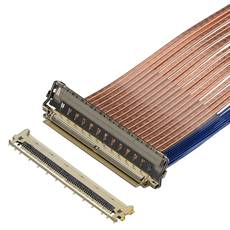
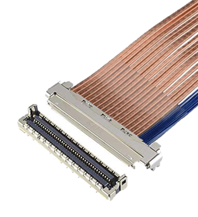
The ultra-thin coaxial cable connector is mainly used to connect digital signals between module boards through the differential transmission mode of the ultra-fine coaxial cable. For proper signal transmission, the center conductor that transmits the signal needs to be connected to the signal circuit on the PCB board through the terminals of the connector. The outer conductor of the cable needs to be electrically connected to the PCB board through the metal part of the connector - the shell. The electrical connection between the outer conductor and the PCB board through the connector shell is called "grounding".

6
Cross-sectional view of the connector in the mated state

5

Search Micro-Coaxial/Twinaxial Connectors                        ​​​​​​​  ​​​​​​​  ​​​​​​​    View Product Matrix      ​​​​​​​  ​​​​​​​  ​​​​​​​  ​​​​​​​  ​​​​​​​        ​​​​​​​  ​​​​​​​  ​​​​​​​  ​​​​​​​  ​​​​​​​ Back to top


2) Preparation process of ultra-fine coaxial male seat harness

The main process of wire harness preparation:

  1. Prepare for Cable Assembly
  2. Install the cable assembly onto the male body assembly and solder the exposed wires to the male signal terminals
  3. Positioning lock assembly (or lock) male seat part
  4. Cap the male housing and solder the required areas to complete the male harness

首先,对极细同轴线进行预处理,以便于线束装配。经过预处理的电缆称为电缆组件。这种预处理简化了连接器的电缆焊接过程,提高了公座线束质量的稳定性。这是在电缆被焊接到连接器之前完成的。

8
电缆组件的准备过程

7


将电缆外层导体焊接于连接器外壳,电缆外层导体通过连接器与PCB板电气连接,以获得良好的接地特性。

9
线束装配过程
(例如: CABLINE®-CA II)
Search Micro-Coaxial/Twinaxial Connectors                        ​​​​​​​  ​​​​​​​  ​​​​​​​    View Product Matrix      ​​​​​​​  ​​​​​​​  ​​​​​​​  ​​​​​​​  ​​​​​​​        ​​​​​​​  ​​​​​​​  ​​​​​​​  ​​​​​​​  ​​​​​​​ Back to top


3) 线缆装配类型

一般来说,下列电缆类型可用于电缆组件(取决于线束制造商):

10全部为极细同轴线:
只使用极细同轴线。电缆组件可以使用不同的电缆直径(直径尺寸范围可能有限制)。


11极细同轴线/电子线混合:
极细同轴线用于信号传输,离散线用于供电。


12接地片和接地手指:
接地片上的接地手指与连接器直接相连,除了可以减少电缆的使用数量外,同时还可以改善线束的电气性能。


Search Micro-Coaxial/Twinaxial Connectors                        ​​​​​​​  ​​​​​​​  ​​​​​​​    View Product Matrix      ​​​​​​​  ​​​​​​​  ​​​​​​​  ​​​​​​​  ​​​​​​​        ​​​​​​​  ​​​​​​​  ​​​​​​​  ​​​​​​​  ​​​​​​​ Back to top


为什么极细同轴线是高速应用的首选?


1) 极细同轴线的特点及应用

随着高速互联网和大容量存储设备使用的增加,我们可以很容易的在个人电脑、平板电脑和智能手机等消费产品上欣赏高质量的图像和视频。设备上需要处理的信息量急剧增加,设备中的信号速度(传输标准)越来越快。

Signal transfer speed

线缆和FPC/FFC主要用于设备中模块板之间传输信号和功率时的跳接连接。在某种程度上,选用线缆还是FPC/FFC是由信号速度(信号传输标准)和传输距离决定的。

* 上述同轴线包括极细同轴电缆和双芯线。

14

随着近年来信号传输速度的提高,极细同轴线在跳接设备中的应用越来越广泛。

15
Search Micro-Coaxial/Twinaxial Connectors                        ​​​​​​​  ​​​​​​​  ​​​​​​​    View Product Matrix      ​​​​​​​  ​​​​​​​  ​​​​​​​  ​​​​​​​  ​​​​​​​        ​​​​​​​  ​​​​​​​  ​​​​​​​  ​​​​​​​  ​​​​​​​ Back to top


2) 极细同轴线的信号传输优势

信号传输特性受若干参数的影响,举例来说,包括阻抗,插入损耗,回波损耗和串音。以下是极细同轴线在高速信号传输时通常被认为具有信号传输优势的一些主要原因。

  • 减少回波损耗:
    极细同轴线的中心导体,绝缘体和外层导体匹配合适,在特定的阻抗下性能稳定。匹配和稳定的阻抗产生低回波损耗。
     
  • 降低插入损耗:
    与FPC/FFC相比,极细同轴线在匹配特定阻抗时可以保证更大的中心导体横截面积,从而最大限度地减少插入损耗。
  • 提高屏蔽性能:
    外层导体起着电磁屏蔽的作用,因此在中心导体上传输的电信号不太容易受到来自外部的电磁波(电磁噪声)的影响。另外,外层导体的屏蔽作用,帮助减少信号之间的串扰。
Search Micro-Coaxial/Twinaxial Connectors                        ​​​​​​​  ​​​​​​​  ​​​​​​​    View Product Matrix      ​​​​​​​  ​​​​​​​  ​​​​​​​  ​​​​​​​  ​​​​​​​        ​​​​​​​  ​​​​​​​  ​​​​​​​  ​​​​​​​  ​​​​​​​ Back to top


3) 极细同轴线的机械性优势

16通常使用极细同轴线的原因是因为它比屏蔽式FPC / FFC具有更高的灵活性,即使弯曲也能保持稳定的电特性。


柔性极细同轴线适合于有转轴的设备,电缆需要在设备内进行布线, 诸如笔记本电脑PC平板转轴和无人机上的移动摄像机。随着包括高清摄像机和面板在内的应用量的上升,伴随着更快的信号传输速度,结合了高速信号特性和机械优势的极细同轴线成为首选解决方案。

1718foldable phone

Search Micro-Coaxial/Twinaxial Connectors                        ​​​​​​​  ​​​​​​​  ​​​​​​​    View Product Matrix      ​​​​​​​  ​​​​​​​  ​​​​​​​  ​​​​​​​  ​​​​​​​        ​​​​​​​  ​​​​​​​  ​​​​​​​  ​​​​​​​  ​​​​​​​ Back to top


为什么 I-PEX 的极细同轴线连接器可以被广泛使用?


1) I-PEX 极细同轴线连接器的特点

I-PEX Connectors 是极细同轴线连接器行业的先驱, 提供适用于多种不同应用的同轴线连接器产品。I-PEX 极细同轴线连接器在 PC 平板连接器行业市场占有率名列前茅。
(CABLINE®-VS 母座 : VESA 标准连接器)
极细同轴线连接器的发展史


多款连接器可选
EMC屏蔽设计, 机械锁扣可选
CABLINE-VS_FAB3-1.jpg CABLINE-VS II CABLINE-CA II PLUS
CABLINE-VS_FAB3-2.jpg CABLINE-VS_FAB3-3.jpg CABLINE-VS_FAB3-4.jpg
CABLINE-VS II 母座
CABLINE-VS 母座
EVAFLEX 5-VS
EMC屏蔽设计(ZenShield®)
CABLINE-VS_FAB3-5.jpg CABLINE-VS_FAB3-6.jpg CABLINE-VS_FAB3-7.jpg CABLINE-CAP CABLINE-VS
CABLINE-VS II 公座 极细同轴线
CABLINE-VS IIF 公座 屏蔽 FPC
CABLINE-VS
公座 
极细同轴线
CABLINE-VSF
公座 
屏蔽/非屏蔽 FPC
EVAFLEX_5-VS
屏蔽/非屏蔽
FPC/FFC
锁扣


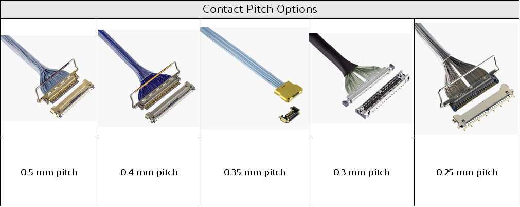
端子间距可选
対插类型可选
CABLINE-VS CABLINE-CA CABLINE-UY CABLINE-UA II CABLINE-CX II without cover CABLINE-CAP
水平
CABLINE-UA II
 垂直 
间距0.5 mm
间距0.4 mm
间距0.35 mm
间距0.3 mm
间距0.25mm
mating type options


Search Micro-Coaxial/Twinaxial Connectors                        ​​​​​​​  ​​​​​​​  ​​​​​​​    View Product Matrix      ​​​​​​​  ​​​​​​​  ​​​​​​​  ​​​​​​​  ​​​​​​​        ​​​​​​​  ​​​​​​​  ​​​​​​​  ​​​​​​​  ​​​​​​​ Back to top


2) I-PEX 屏蔽式连接器的特点

With the development of high-performance, power-saving, and miniaturized electronic equipment, the demand for high-speed signals is increasing, the number of electronic components operating at low voltage is increasing, and the density of installed electronic components is also increasing. If electromagnetic noise is added from the outside, it may cause unnecessary current in the internal circuit of the device, causing failure or damage of high-performance electronic components, and may also cause damage to electronic devices. .In addition, in electronic devices with wireless communication functions (such as laptops, tablets, and mobile phones), electromagnetic waves generated inside the devices increase the noise of the wireless communication circuit, thereby degrading the antenna reception performance.
.In this case, in general, the measure against electromagnetic noise inside the equipment is to physically shield the electromagnetic noise by incorporating an electromagnetic noise filter element into the circuit and/or adding a metal shield to the element.

With the introduction of small devices mounting high-density components, and the emergence of high-speed signals in these devices, it is necessary to take measures against electromagnetic noise at device jumpers. I-PEX has developed a series of connectors that solve the problem of electromagnetic noise in the connector, with suitable grounding structure and covering layer, including the mounting position of the signal terminal tail with metal shielding ( ZenShield ® ) . This solution is widely adopted by many customers to prevent electromagnetic interference, especially on high-performance devices equipped with wireless communication functions such as Wi-Fi®, GPS, LTE, etc.

2122


White Paper:  Electromagnetic Interference Shielding Cover Technical Report

White Paper: Techniques for mitigating intrapair skew induced EMI with shielded.

White Paper: Achieving high speed transmission by improving SI performance with a paddle card.


For more information, please contact your local I-PEX sales representative.


Search Micro-Coaxial/Twinaxial Connectors                        ​​​​​​​  ​​​​​​​  ​​​​​​​    View Product Matrix      ​​​​​​​  ​​​​​​​  ​​​​​​​  ​​​​​​​  ​​​​​​​        ​​​​​​​  ​​​​​​​  ​​​​​​​  ​​​​​​​  ​​​​​​​ Back to top