Paddle Card Technology for Micro Coax Cable Harness - Improving SI Performance
Background
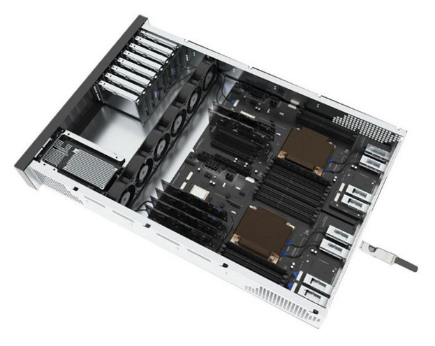
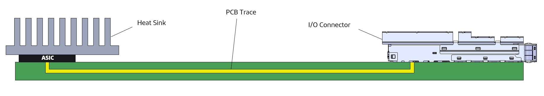
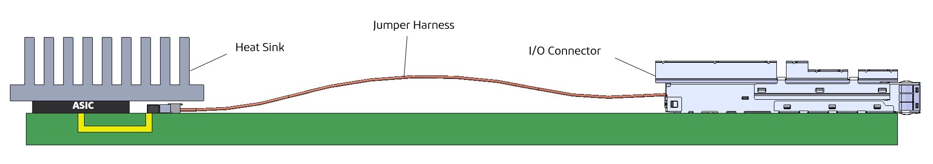
Infrastructure telecommunication equipment, such as servers and switches, has become increasingly faster in the enterprise market. Therefore, signal integrity (SI) performance must be improved for each component used in these systems. Improvement of SI performance has a role in improving equipment performance. The challenge is that conventional PCB trace transmission has large insertion losses with limited transmission distance. Jumper harnesses that use cables to solve these problems are attracting attention as a possible solution. Figure 1 shows the conventional PCB trace transmission from ASIC to I/O. Figure 2 shows the jumper harness transmission from ASIC to I/O, instead of PCB tracing as in Figure 1. This solution can reduce transmission loss by minimizing the PCB trace length using a low-profile connector, which can be placed under the heat sink (closer to ASIC), and with a directly terminated cable to an I/O connector.
THE CHALLENGE
The premise is that the transmission loss must be improved while lowering the connector height. The reason for lowering the connector size is that the connector needs to be placed under the heat sink to bring it closer to the ASIC (as shown in Fig. 2) to reduce transmission loss. Transmission speed is assumed to be 64 Gbps PAM4 (frequency 16 GHz).
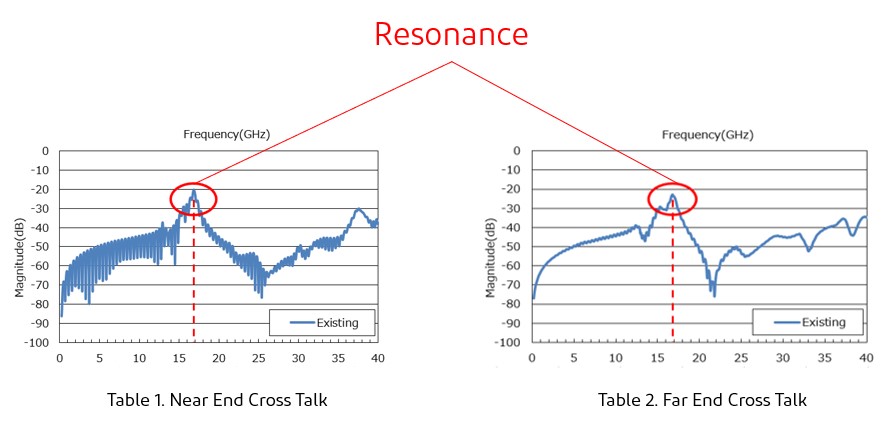
Existing micro-coaxial connector products have no transmission quality problems up to around 13 GHz. However, resonance occurs around the target frequency of 17 GHz, resulting in deteriorated transmission quality. Tables 1 and 2 show near-end crosstalk (NEXT) and far-end crosstalk (FEXT) for conventional products. The red circles indicate resonance points.
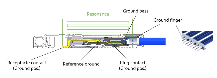
The resonance frequency that occurs is dependent on the length of the ground return path. If the wavelength “λ” is long, the resonance frequency occurs in the low frequency band. Conversely, if the wavelength “λ” is short, the resonance frequency occurs in the high frequency band. Figure 3 shows the structure of the mating condition of the plug and receptacle of conventional micro-coaxial connector products. Due to the structure of the connector the ground path cannot be easily set. Cable and terminal ground paths are connected by ground fingers. The area in green indicates the resonance area.
THE COUNTERMEASURES
By replacing the existing plug connector with a paddle card (FPC), the ground path can be easily installed. This leads to a stronger ground path and a shorter resonance area.ed by ground fingers. The area in green indicates the resonance area.
WHAT IS A PADDLE CARD?
A paddle card can be mated with a mating connector, and PCB or FPC can be designed for the plug circuit. Paddle cards are easy to add to ground structures, improving ground return. Impedance matching is simplified, and signal integrity is improved at higher frequencies. Figure 4 shows the appearance of a conventional micro-coaxial harness. Figure 5 shows the appearance of a micro-coaxial harness with paddle card. Mating contacts (pads) are configured on the paddle card.
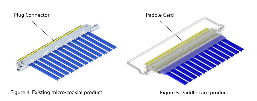
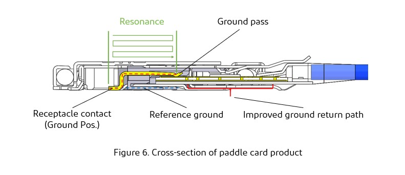
Figure 6 shows the structure of the mating condition of the plug and receptacle of the paddle card product. It is possible to set up many ground paths through the paddle card (FPC), giving it greater design flexibility. The area in green indicates the resonance area.
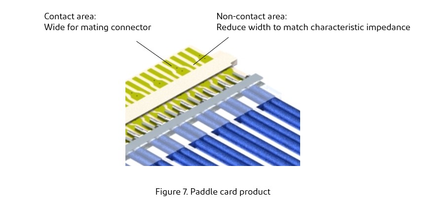
By using a paddle card, the signal line width can be adjusted to specific requirements and the characteristic impedance can be easily matched. Figure 7 shows a micro-coaxial cable connected to a paddle card. The connection method between the paddle card and the cable is achieved by soldering. The width of the paddle card terminal must be wide for mating contact with the receptacle. The terminals can be narrower at non-contact areas to support characteristic impedance control.
THE EFFECT
Transmission characteristics, simulation conditions
Analytical software: Ansys HFSS 19.0
- Frequency: 0-40 GHz
- Cable: Micro-coaxial cable, AWG #36, 42.5 ohm
- Cable length: 254 mm (10 inches)
- Connector with both ends
- Pin assignment: GSSGSSGSSG (G: Ground, S: Signal)
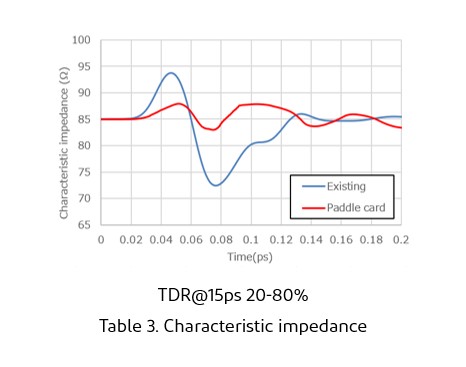
・Improved characteristic impedance
Existing product was 73 ohm-94ohm. However, the paddle card product has improved to 84-87 ohm. Table3 shows a comparison of the characteristic impedance of conventional and improved product using a paddle card.
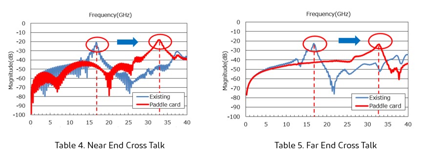
・Improved NEXT and FEXT
Paddle card products can shift the resonance frequency.
As shown in the table below, the resonance frequency has been shifted from 17 GHz to 33 GHz. Thus, transmission up to the 25 GHz band is now possible. Tables4 and 5 show results for NEXT and FEXT. These are comparisons between existing product and improved product with a paddle card. The red circles indicate resonance points.
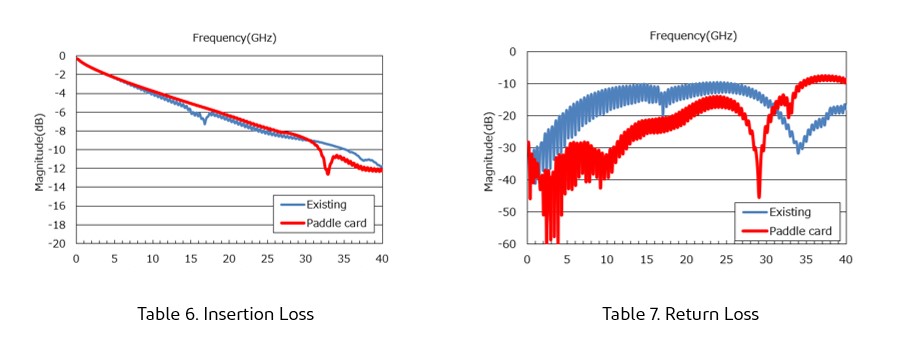
・Improved insertion loss and return loss
Insertion loss and return loss also improved by improving characteristic impedance. Tables 6 and 7 show results for insertion loss and return loss. These are comparisons between existing product and the improved product with a paddle card.
Summary
This confirms that SI performance has been improved by changing from the existing product to a paddle card. In a layout where internal space is limited, such as server and switch, a paddle card with high SI performance, combined with a low connector height, is an effective solution.
CABLINE®-CAP Product page: https://www.i-pex.com/product/cabline-cap
CABLINE®-CA IIP PLUS Product page: https://www.i-pex.com/product/cabline-ca_IIp_plus