

What is MIPI?
MIPI Alliance and Specifications
The Mobile Industry Processor Interface (MIPI) Alliance organization was established in 2003 with the purpose of standardizing the hardware and software interfaces for smart phones. Today, the organization offers a comprehensive portfolio of specifications to define interface between chipsets, processors, and peripherals (sensors and displays) in mobile devices and automobiles.
MIPI Alliance specifies six types of interface for mobile devices: Physical Layer, Multimedia, Chip-to-Chip, Device Control & Data Management, System Debugging, and Software Integration. Each interface is aimed at achieving the fundamental characteristics of a mobile device: low power, high bandwidth, low pin count, and low electromagnetic interference.
• Physical Layer defines the electrical characteristics of the signals being transmitted and received
(e.g. C-PHY, D-PHY, M-PHY, etc.)
• Multimedia defines the protocols to encode and decode signals for peripheral devices
(e.g. CSI-2, DSI-2, etc.)
• Chip-to-Chip protocolizes the data being transmitted and received between MIPI processors and components
(e.g. DigRF, UniPro, etc.)
• Device Control & Data Management standardizes the control signals used to manage and monitor MIPI sub-systems
(e.g. I3C, RFFE, SPMI, BIF, etc.).
• System Debugging standardizes the debug, test, and diagnostics access to MIPI sensors and peripherals
(e.g. Debug over I3C, USB, etc.).
• Software Integration standardizes software-to-hardware interface to ensure MIPI components are controlled uniformly by the operating system, drivers, and firmware
(e.g. DisCo, HCI, TCRI, etc.).
MIPI D-PHY and C-PHY
The physical specifications, D-PHY and C-PHY, are primarily written for interfacing video components (e.g. cameras and displays). These specifications, devised for scalable bandwidth and low power, define the physical and electrical interface between MIPI devices, including low-level timing and protocols. The transmission rates for standard channels are listed below:
D-PHY Transmission Rate (Standard Channel)
• 2.5 Gbps (v1.2)
• 4.5 Gbps (v2.X)
• 9.0 Gbps (v3.X)
C-PHY Transmission Rate (Standard Channel)
• 6.4 Gbps (v1.1)
• 8.0 Gbps (v1.2)
• 13.7 Gbps (v2.X, v3.0)
• 17.8 Gbps (v3.1)
Interconnecting MIPI D-PHY and C-PHY
|
|
Physical Connection (between 2 devices) |
| D-PHY | • 1 differential signal pair per 1 lane • 1 differential clock pair (optional) • 4 lanes maximum |
| C-PHY | • 3 single-ended signals per 1 lane • 3 lanes maximum |
D-PHY Interface
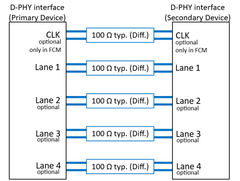
A single D-PHY interface supports up to four differential signal lanes (1 mandatory, 3 optional). The clock signal is supplied by the primary device in either Forwarded Clock Mode (FCM) or Embedded Clock Mode (ECM). In FCM, the clock signal is transmitted over a dedicated differential lane. In contrast, the clock is recovered from the embedded data stream when operating in ECM; hence, ECM eliminates the need for a dedicated clock lane. The D-PHY specification requires a differential connection for each lane with an intended impedance of 100 ohm; however, the differential output impedance of a transmitter can vary from 80 ohm to 125 ohm.
C-PHY Interface
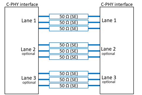
The C-PHY protocol encodes and decodes data by detecting the voltage differences among three single-ended connections at the receiver. Consequently, each lane consists of 3 single-ended connections as shown in the diagram below. The C-PHY specification requires each single-ended connection to be 50 ohm. This architecture results in differential-mode and common-mode impedances of 100 ohm and 25 ohm, respectively, for signal transmission. The clock is recovered from the embedded data stream; hence, there is no clock connection in C-PHY interface.
Connectors for D-PHY and C-PHY Interfaces Maximizing Signal Integrity (SI)
The Signal Integrity (SI) of D-PHY and C-PHY links becomes critical in achieving their specified transmission rates. In high-speed transmission media, the following electrical phenomena can degrade SI performance.
• Insertion Loss (IL)
• Return Loss (RL)
• Near-end Crosstalk (NEXT)
• Far-end Crosstalk (FEXT)
• Electromagnetic Interference (EMI)
The insertion loss (IL) is primarily determined by the dielectric properties of the insulating material and the series resistance of the signal path, whereas the return loss (RL) results from the impedance mismatches between components along the signal path. The crosstalk (NEXT and FEXT) is caused by electromagnetic coupling between adjacent signal paths. In systems using coaxial cables, crosstalk typically occurs at the connectors, where the signal conductors are in proximity. All these SI parameters – IL RL, NEXT, and FEXT – can be optimized in the connector design by carefully controlling the material properties and construction geometry.
Securing Mated Connection
The SI performance of a mated connection can only be guaranteed when the plug and receptacle are securely mated and mechanically retained. Therefore, adequate retention force is essential for preserving the SI of a mated connection. The retention force can dramatically improve by adding a mechanical lock on the plug to engage the receptable. The mechanical lock on connectors may become a necessity in mobile applications where the interconnects must withstand high levels of shock and vibration.
Suppressing EMI
In single-ended transmission, EMI is primarily caused by high-frequency energy leaking through discontinuities or openings in shielding. These openings typically occur near the mated connection due to improper termination or inadequate shielding mechanism.
In differential signaling, EMI primarily originates from unsuppressed common-mode signals, which are largely generated by mode conversion at the mated connection. High-speed connectors are designed to preserve signal balance and minimize mode conversion; however, some degree of mode conversion is unavoidable due to the manufacturing tolerance of the shield termination.
The most effective way to mitigate EMI radiation and susceptibility is to completely enclose the signal paths within the connector using ground. I-PEX offers connectors that are fully shielded to meet the stringent requirements of EMI certification.
I-PEX Connector Solutions
I-PEX specializes in manufacturing connectors and cable assemblies engineered to maximize signal integrity (SI), minimize electromagnetic interference (EMI), and provide high retention force. These characteristics make our solutions well suited for high-speed interfaces such as D-PHY and C-PHY. Our CABLINE® and NOVASTACK® series have long served the industry for interconnecting D-PHY and C-PHY devices, and their key features are highlighted below.
CABLINE® Series (CABLINE®-CA II & CABLINE®-UM)
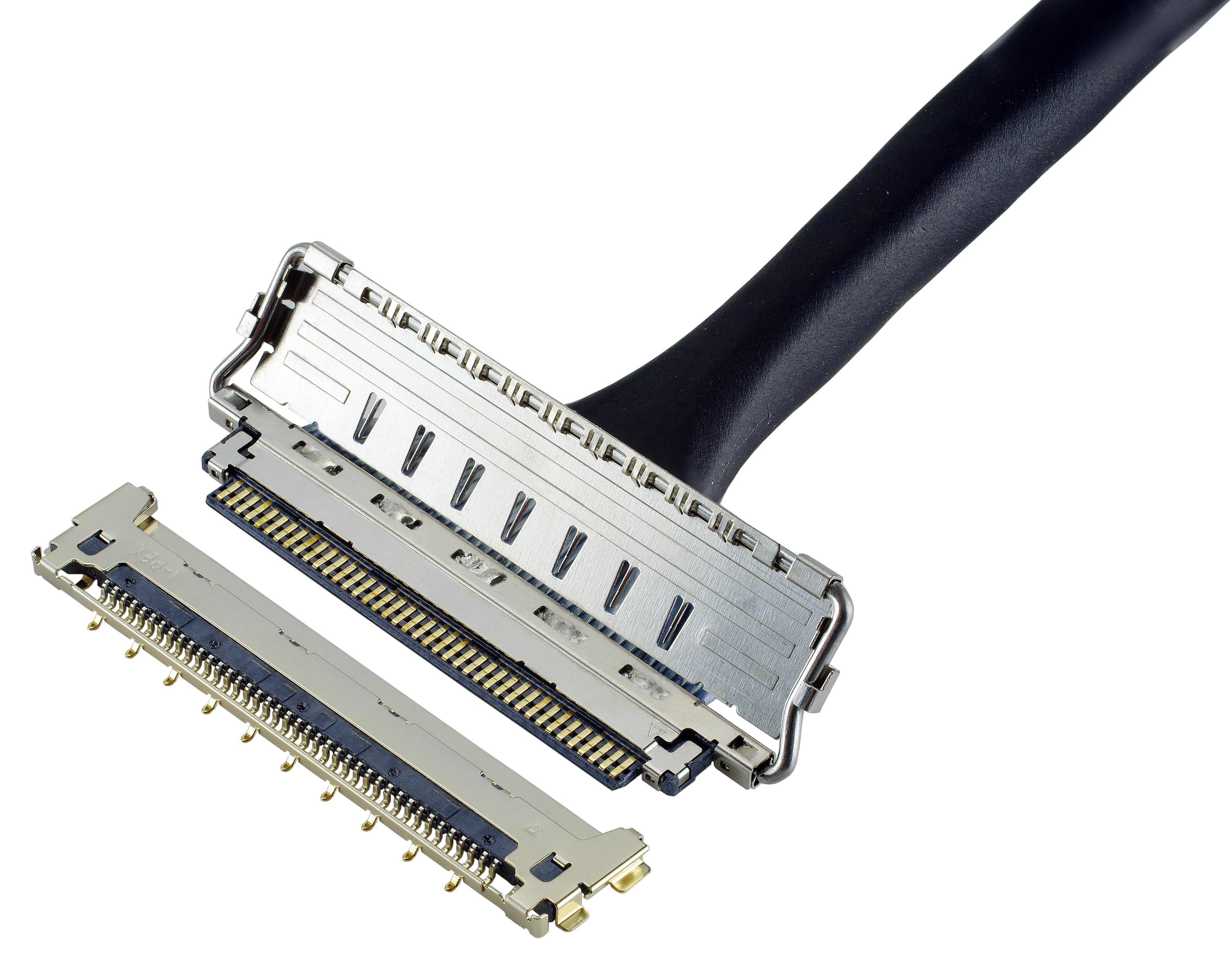
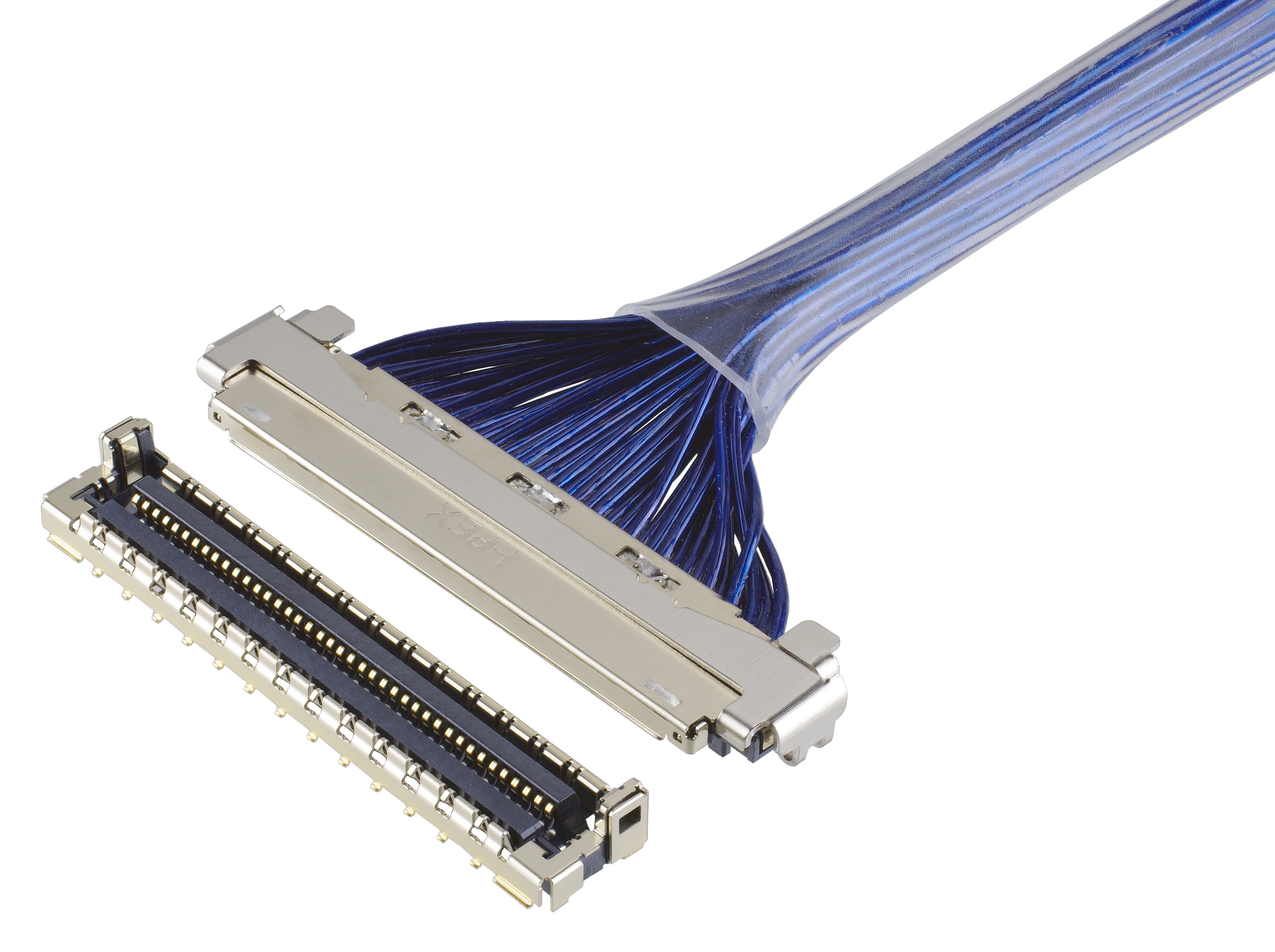
I-PEX’s CABLINE® series was the first micro-coaxial connectors in the industry. Since its introduction in 1996, the CABLINE® connectors have been widely adopted in interconnecting high-speed interfaces such as USB4, Thunderbolt, PCIe, MIPI D-PHY, and MIPI C-PHY.
|
|
| CABLINE® Series | |||
| CABLINE®-CA II | CABLINE®-UM | ||
| Pitch | 0.4 mm | 0.4 mm | |
| Mating Type / Direction | Horizontal | Vertical (Right Angle) | |
| Mated Height | 0.95 +/- 0.15 mm | 2.2 +/- 0.15 mm | |
| Available Pin Count | 20, 30, 40, 50 | 30, 40, 50, 60, 70 | |
| Applicable Standards | Up to 32 Gbps/lane | Up to 40 Gbps/lane PAM3 | |
| Available Cable Size | Micro-coaxial Twinaxial Discrete |
AWG 36*, 38, 40, 42, 44 AWG 40, 42 AWG 34, 36 |
|
*Characteristic impedance unmatching.
The CABLINE®-CA II and CABLINE®-UM connectors in the series are popular for interconnecting D-PHY and C-PHY interfaces because of their key features below:
• Excellent signal integrity (CABLINE®-CA II: up to 32 Gbps/lane, CABLINE®-UM: 40 Gbps/lane PAM3)
• High retention force (mechanical lock)
• Superior EMI suppression (360° shielding when mated)
• High operating temperature (-40 to 105 °C)
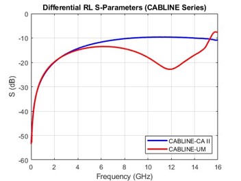
The CABLINE®-CA II and CABLINE®-UM connectors provide mechanical stability and signal integrity required for high-speed links in mobile devices. Another advantage of the CABLINE® connectors is the manufacturing flexibility; the cable assemblies can be configured in different pin counts and cable types. The standard options for pin count and coaxial cable size are tabulated above. The simulated SI performances of the CABLINE®-CA II and CABLINE®-UM connectors are shown below.
| CABLINE®-CA II & CABLINE®-UM | |
| Simulation Condition CST Studio Suite 2023 SP5 Freq Range: 0.1 GHz to 16 GHz Cable: MCX AWG 38 |
Pin Configuration: G-S-S-G |
| Differential Insertion Loss | |
|
Reference Z = 42.5 ohm (SE) / 85 ohm (DIFF) 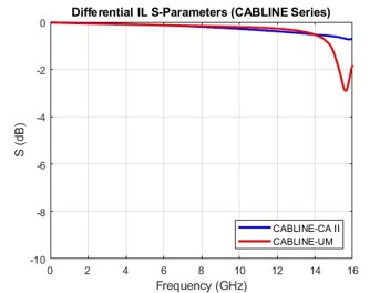 |
Reference Z = 50 ohm (SE) / 100 ohm (DIFF) 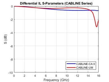 |
| Differential Return Loss | |
|
Reference Z = 42.5 ohm (SE) / 85 ohm (DIFF) 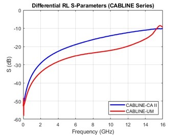 |
Reference Z = 50 ohm (SE) / 100 ohm (DIFF)
|
| CABLINE®-CA II & CABLINE®-UM | |
| Simulation Condition CST Studio Suite 2023 SP5 Freq Range: 0.1 GHz to 16 GHz Cable: MCX AWG 38 |
Pin Configuration: G-S-S-G |
| Differential Near-end Crosstalk | |
|
Reference Z = 42.5 ohm (SE) / 85 ohm (DIFF) 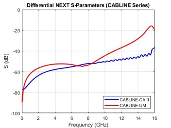 |
Reference Z = 50 ohm (SE) / 100 ohm (DIFF) 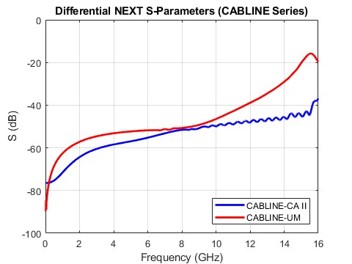 |
| Differential Far-end Crosstalk | |
|
Reference Z = 42.5 ohm (SE) / 85 ohm (DIFF) 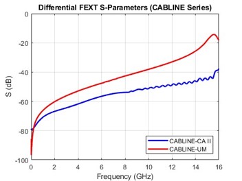 |
Reference Z = 50 ohm (SE) / 100 ohm (DIFF) 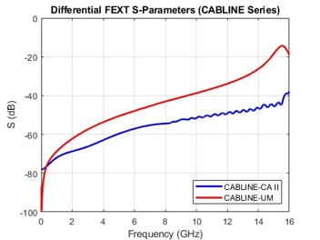 |
a
| CABLINE®-CA II & CABLINE®-UM | |
| Simulation Condition CST Studio Suite 2023 SP5 Freq Range: 0.1 GHz to 16 GHz Cable: MCX AWG 38 |
Pin Configuration: S-S-S-S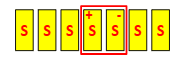 |
| Differential Insertion Loss | |
|
Reference Z = 42.5 ohm (SE) / 85 ohm (DIFF) 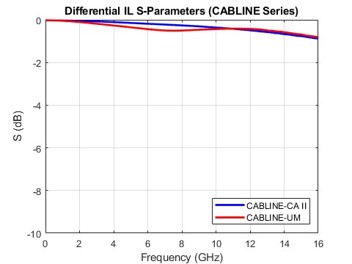 |
Reference Z = 50 ohm (SE) / 100 ohm (DIFF) 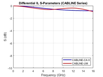 |
| Differential Return Loss | |
|
Reference Z = 42.5 ohm (SE) / 85 ohm (DIFF) 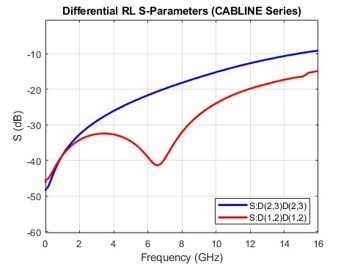 |
Reference Z = 50 ohm (SE) / 100 ohm (DIFF) 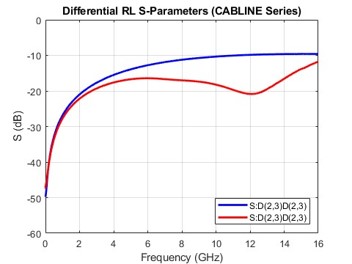 |
| CABLINE®-CA II & CABLINE®-UM | |
| Simulation Condition CST Studio Suite 2023 SP5 Freq Range: 0.1 GHz to 16 GHz Cable: MCX AWG 38 |
Pin Configuration: S-S-S-S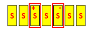 |
| Differential Insertion Loss | |
|
Reference Z = 42.5 ohm (SE) / 85 ohm (DIFF) 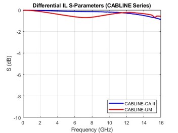 |
Reference Z = 50 ohm (SE) / 100 ohm (DIFF) 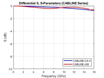 |
| Differential Return Loss | |
|
Reference Z = 42.5 ohm (SE) / 85 ohm (DIFF) 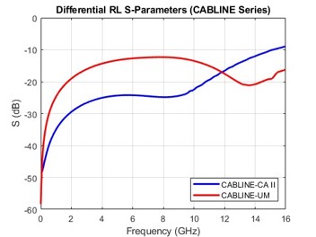 |
Reference Z = 50 ohm (SE) / 100 ohm (DIFF) 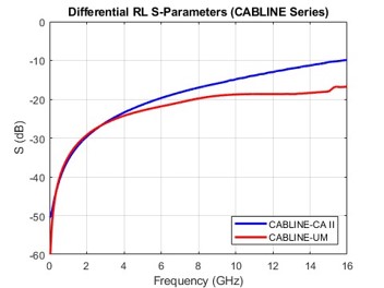 |
NOVASTACK® Series (NOVASTACK® 35-HDP & NOVASTACK® 35-HDN)
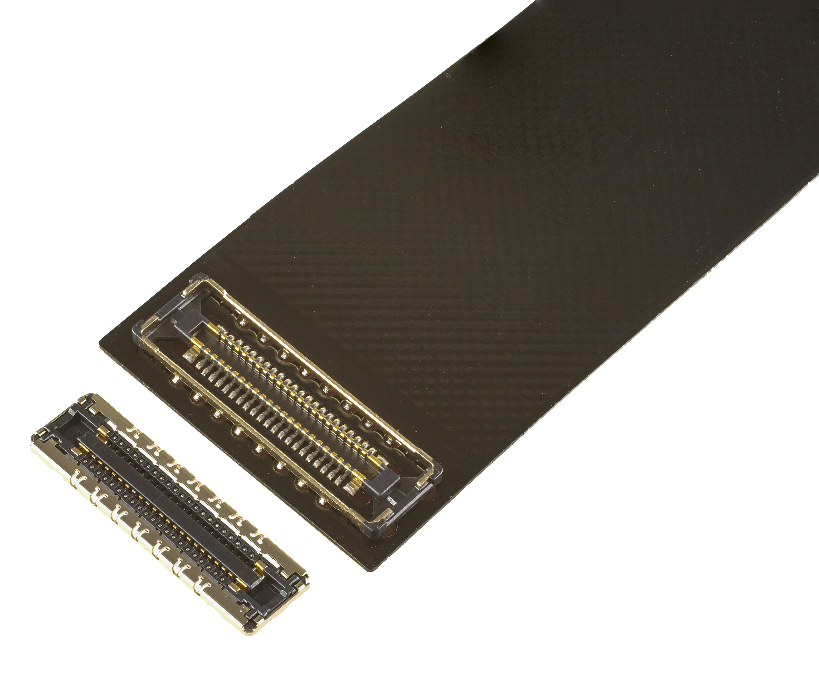
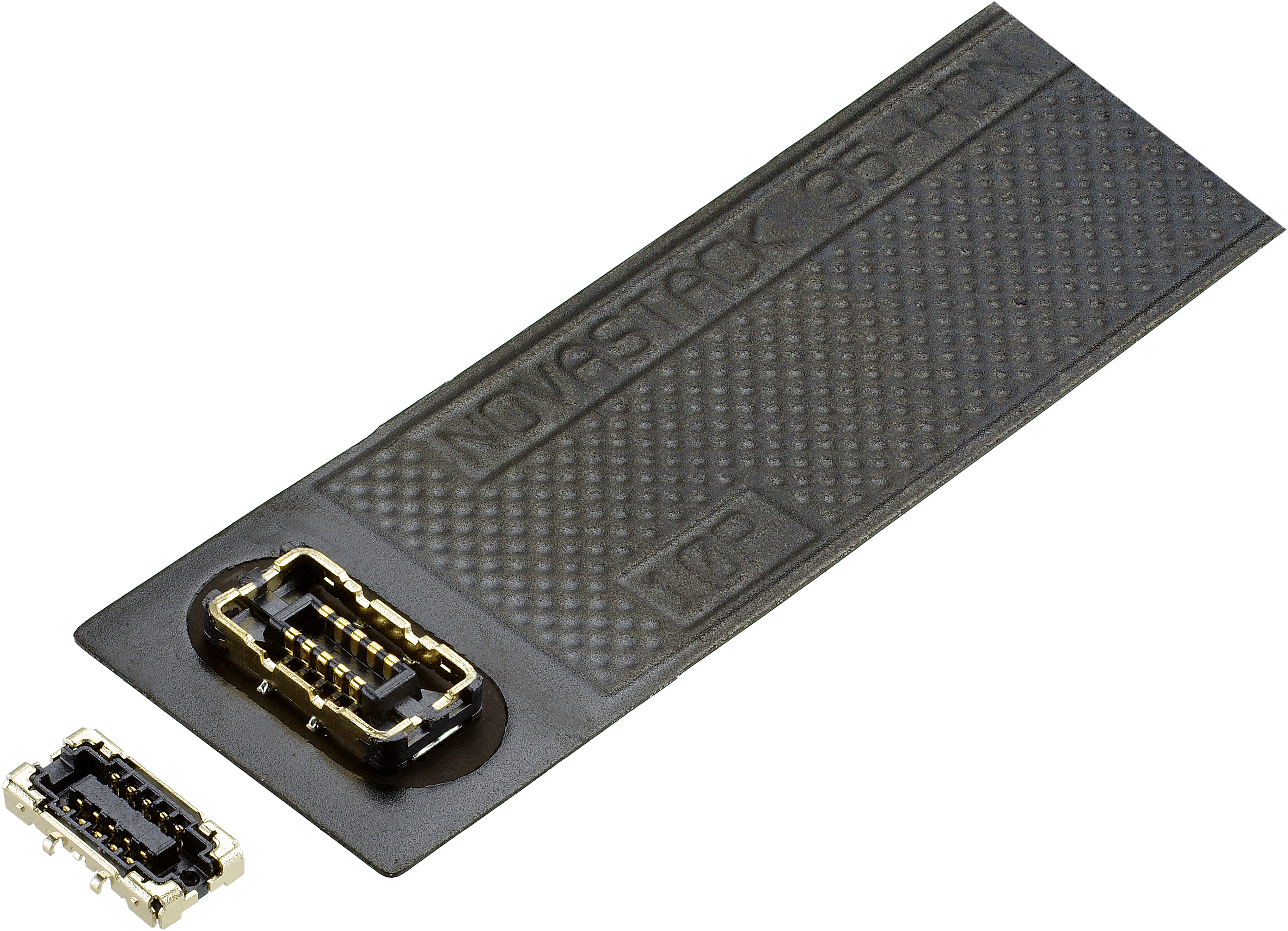
I-PEX’s NOVASTACK® Series consists of high-density connectors designed for board-to-board and board-to-FPC connections. The NOVASTACK® connectors can support frequencies up to 20 GHz and are available in various heights and FPC types.
|
|
| NOVASTACK® Series | |||
| NOVASTACK® 35-HDP | NOVASTACK® 35-HDN | ||
| Pitch | 0.35 mm | 0.35 mm | |
| Mated Height | 0.7 +/- 0.05 mm | 0.7 +/- 0.05 mm | |
| Applicable Standards | Up to 40 Gbps | Up to 30 Gbps | |
| Available Pin Count | Signal | 16, 28, 34, 42, 56, 62 | 10, 20, 30 |
| Power | 4 | - | |
The NOVASTACK® 35-HDP and NOVASTACK® 35-HDN connectors in the series are ideal for routing C-PHY and D-PHY signals between PCBs in mobile devices because of their key features below:
• Excellent signal integrity (up to 40 Gbps)
• High signal density (up to 62 pins)
• Low profile (0.7 +/- 0.05 mm mated height)
• Superior EMI suppression (360° shielding when mated)
• Dedicated power pins (4 pins, 4.5 A/pin, only for NOVASTACK® 35-HDP)
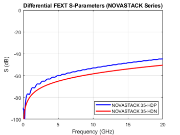
The absence of a physical lock typically does not compromise the stability of board-to-board connections because the boards are usually mounted. However, the board-to-FPC connections require sufficient retention force to maintain a reliable connection. The NOVASTACK® 35-HDP and NOVASTACK® 35-HDN connectors are designed to withstand harsh operating environments even without a locking mechanism. The available pin counts are listed in the table above. The simulated SI performances of the NOVASTACK® 35-HDP and NOVASTACK® 35-HDN connectors are shown below.
| NOVASTACK® 35-HDP & NOVASTACK® 35-HDN | |
| Simulation Condition CST Studio Suite 2023 SP5 Freq Range: 0.1 GHz to 20 GHz |
Pin Configuration: G-S-S-G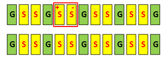 |
| Differential Insertion Loss | |
|
Reference Z = 42.5 ohm (SE) / 85 ohm (DIFF) 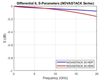 |
Reference Z = 50 ohm (SE) / 100 ohm (DIFF) 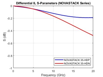 |
| Differential Return Loss | |
|
Reference Z = 42.5 ohm (SE) / 85 ohm (DIFF) 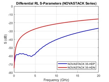 |
Reference Z = 50 ohm (SE) / 100 ohm (DIFF) 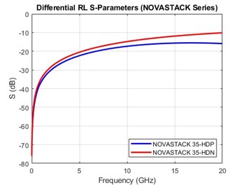 |
| NOVASTACK® 35-HDP & NOVASTACK® 35-HDN | |
| Simulation Condition CST Studio Suite 2023 SP5 Freq Range: 0.1 GHz to 20 GHz |
Pin Configuration: G-S-S-G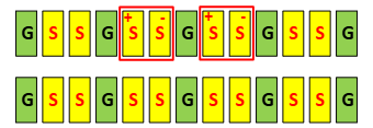 |
| Differential Near-end Crosstalk | |
|
Reference Z = 42.5 ohm (SE) / 85 ohm (DIFF) 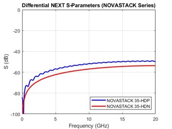 |
Reference Z = 50 ohm (SE) / 100 ohm (DIFF) 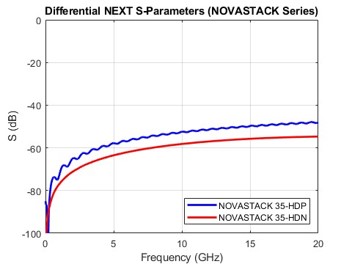 |
| Differential Far-end Crosstalk | |
|
Reference Z = 42.5 ohm (SE) / 85 ohm (DIFF) 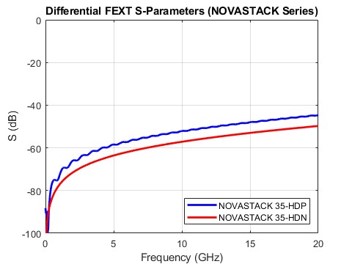 |
Reference Z = 50 ohm (SE) / 100 ohm (DIFF)
|
| NOVASTACK® 35-HDP & NOVASTACK® 35-HDN | |
| Simulation Condition CST Studio Suite 2023 SP5 Freq Range: 0.1 GHz to 20 GHz |
Pin Configuration: G-S-S-G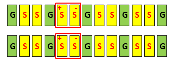 |
| Differential Near-end Crosstalk | |
|
Reference Z = 42.5 ohm (SE) / 85 ohm (DIFF) 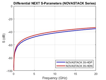 |
Reference Z = 50 ohm (SE) / 100 ohm (DIFF) 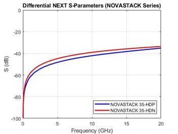 |
| Differential Far-end Crosstalk | |
|
Reference Z = 42.5 ohm (SE) / 85 ohm (DIFF) 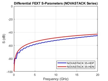 |
Reference Z = 50 ohm (SE) / 100 ohm (DIFF) 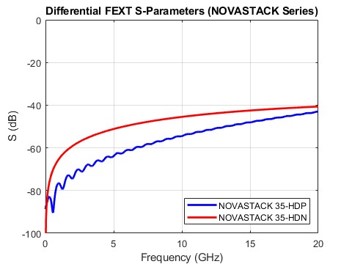 |
| NOVASTACK® 35-HDP & NOVASTACK® 35-HDN | |
| Simulation Condition CST Studio Suite 2023 SP5 Freq Range: 0.1 GHz to 20 GHz |
Pin Configuration: S-S-S-S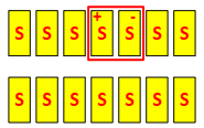 |
| Differential Insertion Loss | |
|
Reference Z = 42.5 ohm (SE) / 85 ohm (DIFF) 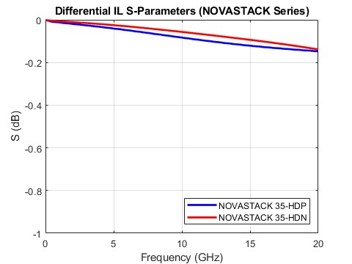 |
Reference Z = 50 ohm (SE) / 100 ohm (DIFF) 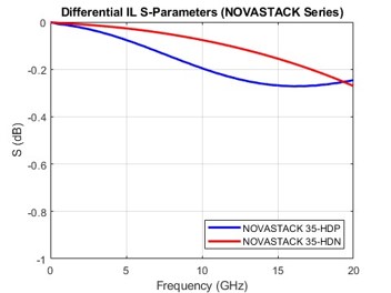 |
| Differential Return Loss | |
|
Reference Z = 42.5 ohm (SE) / 85 ohm (DIFF) 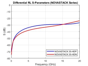 |
Reference Z = 50 ohm (SE) / 100 ohm (DIFF) 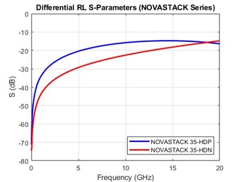 |
| NOVASTACK® 35-HDP & NOVASTACK® 35-HDN | |
| Simulation Condition CST Studio Suite 2023 SP5 Freq Range: 0.1 GHz to 20 GHz |
Pin Configuration: S-S-S-S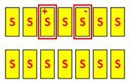 |
| Differential Insertion Loss | |
|
Reference Z = 42.5 ohm (SE) / 85 ohm (DIFF) 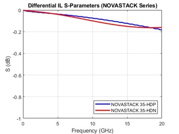 |
Reference Z = 50 ohm (SE) / 100 ohm (DIFF) 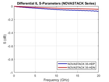 |
| Differential Return Loss | |
|
Reference Z = 42.5 ohm (SE) / 85 ohm (DIFF) 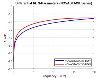 |
Reference Z = 50 ohm (SE) / 100 ohm (DIFF) 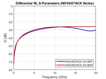 |
Cable Assemblies for MIPI D-PHY and C-PHY
The connectors in a cable assembly should maximize signal integrity (SI), minimize electromagnetic interference (EMI), and provide adequate retention force, as discussed in the previous sections. When selecting cables for the assemblies, I-PEX offers two options: micro-coaxial (MCX) cables and flexible printed circuit (FPC) cables. The CABLINE® series is mainly designed for MCX cables, and the NOVASTACK® series is designed for FPC cables and board-to-board connections.
| Micro-Coaxial (MCX) Cables |
Flexible Printed Circuit (FPC) Cables |
|
| IL per length | Low | Medium |
| Thickness | Thin | Very Thin |
| Flexibility | Excellent | Excellent (directional) |
The following must be considered when selecting the cables.
• Characteristic Impedance – The characteristic impedance of the cables should match that of the connectors and the transmitter/receiver to minimize signal reflections (RL). The characteristic impedance should also remain stable under mechanical and environmental stresses, such as bending, twisting, and thermal shock.
• Insertion Loss (IL) – The insertion loss of the cable assembly (connectors and cables), when referenced to the system impedance, must accommodate the system’s IL budget.
• Return Loss (RL) – The return loss of the cables should be minimized when referenced to the cable's characteristic impedance.
Conclusion
I-PEX specializes in designing and manufacturing high-speed interconnects with customizable pin counts and cable types. Some of our solutions are well suited for D-PHY and C-PHY connections in mobile devices. This article highlighted CABLINE®-CA II, CABLINE®-UM, NOVASTACK® 35-HDP, and NOVASTACK® 35-HDN; however, I-PEX has other families of products that deliver comparable signal integrity, mechanical reliability, and design flexibility. For more information, please contact us.


