How to Read I-PEX Connector Product Drawings
Product drawings are the language of engineers. The engineers communicate through the drawings, and the manufacturing department processes and assembles according to the drawings. Ambiguity in the drawing will affect the design, development and production applications. Reading and understanding of product drawings is crucial in the design work of engineers and production line production.
Although there are general standards to follow when creating product drawings, the drawings vary in different companies. This article will help you better understand I-PEX connector product drawings, making your design and development work, and communication with your production line more efficient.
Finding Product Drawings
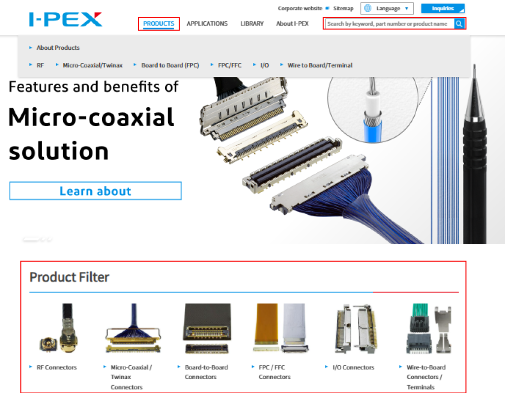
The I-PEX product drawings can be viewed and downloaded from our company's official website ( www.i-pex.com ).
Click on “Product” on the header menu and choose product category or click on the product image on Product Filter section on the top of the page. You can also find product page by entering a product name or the part number of the product you are looking for from the search box on the right top of the page.
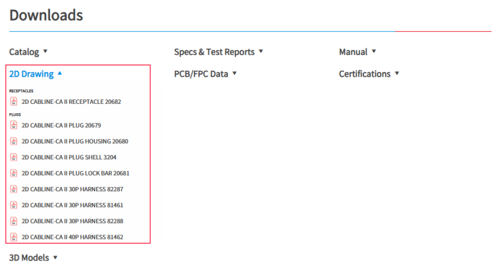
When you open the product page, select "2D Drawings" in the "Download" area. You will see drawings related to this product. Select the drawings you want to download.
You can also contact the relevant I-PEX sales reps and technical personnel in your regions and ask for the required drawings. ( Where we are )
Structure of Connector Product Drawings
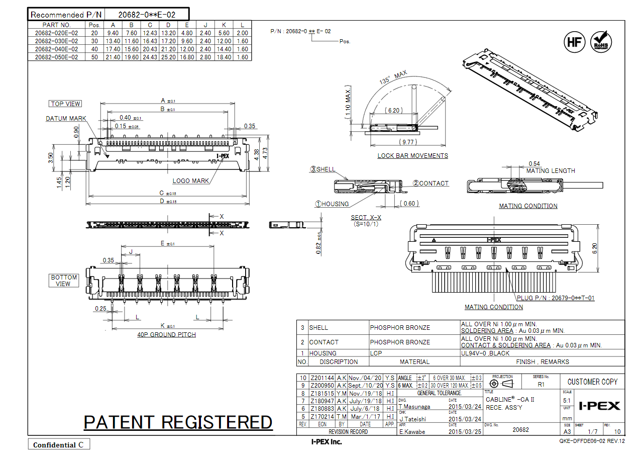
Let's take a look at the drawing for the CABLINE®-CA II series receptacle (20682) as an example.
The I-PEX product drawing usually has several pages and each page is divided into certain areas, as shown in the picture below.

Page 1
In the lower right corner of the first page of the drawing, you will see two tables. One is the title table at the bottom, which is outlined in red, and the other is the part name and material sheet (also known as BOM) outlined in green.
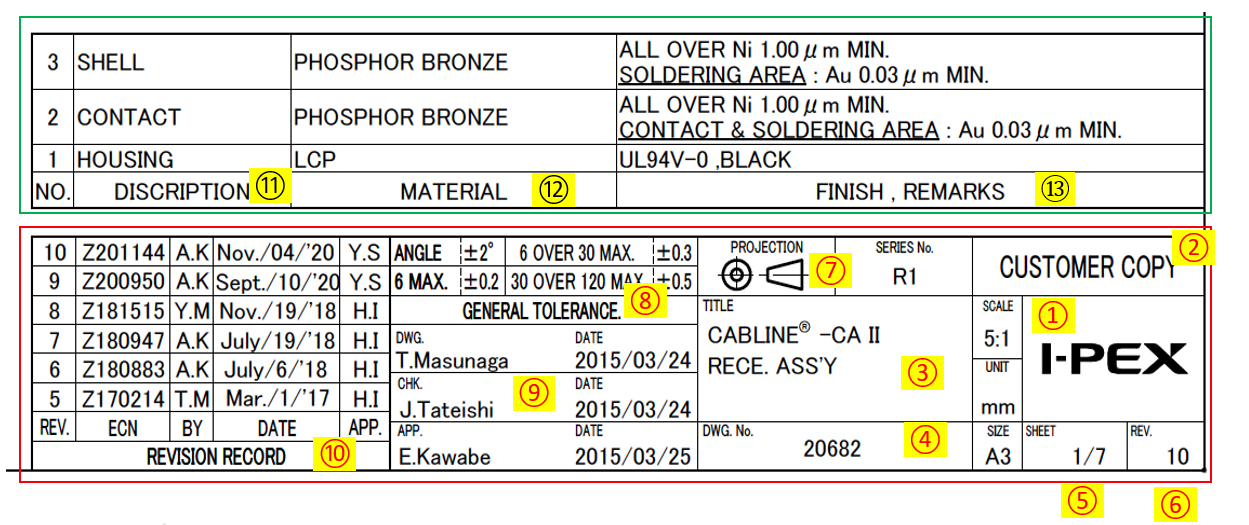
- Descriptions of Title Table
1. I-PEX logo
2. “CUSTOMER COPY” indicates that this drawing is for customers use
3. Name of this product
4. The first 5 digits of the part number of this product
5. Page number / total sheet number
6. Revision number
7. Explanation of the projection method used to generate this drawing.
(All I-PEX drawings are based on trigonometry.)
8. General tolerances for dimensions not marked with exact tolerances
9. Member of the initial product design and development team in I-PEX.
10. Record of changes
- Description of Part Name and Material Sheet (BOM) Table
11. Name of the parts that make up this product.
12. The material name of the above parts
13. Finish and Remarks area indicates flammability grade and color for housing, and specifications for plating specifications for metal parts, for example
- Parts Number and Dimension Table
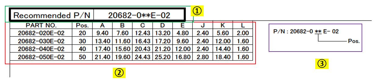
1. Recommended P/N (Parts Number).
Some products have different types and revisions, so they may have multiple part numbers. The Recommended Parts Numbers often indicates the most popular, or latest type of the product. I-PEX recommends choosing this Recommend Part Number unless you have a specific reason to use another type.
(The mark “**” in recommended P/N indicates position number.)
2. Available pin counts and list of dimensions that differs based on the pin counts.
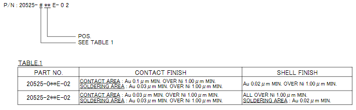
3. Parts number structure information.
Types may be illustrated with additional table if the product has a variety of types.
- Middle Section of the Drawing
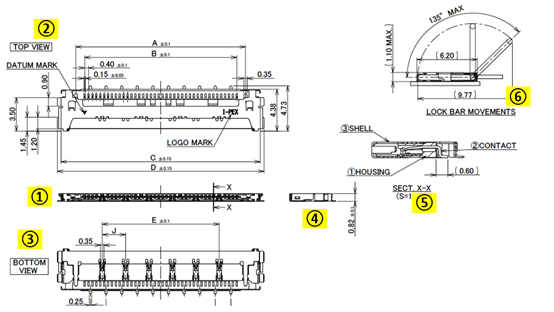
1– 4. Product appearance and size from different angles, based on trigonometry.
5. Sectional view of the product, from which the composition and relative position of parts.
6. Illustrating the movement track of the pull bar if the product has a pull bar function.
- Mating Condition Diagram Area
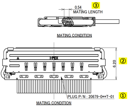
1. The part number of the product that mates to the product in the drawing.
(In this case, CABLINE®-CA II PLUG assembly parts number that mates to the receptacle.)
2. Size of the mating condition of the connector.
(Depth for horizontal connector and height for vertical connector.)
3. Illustrates the wiping length of the contacts, which has a certain relationship with the contact reliability of the product.
Product Specification Page
The product specification page lists the relative important electrical and mechanical specifications of the product.
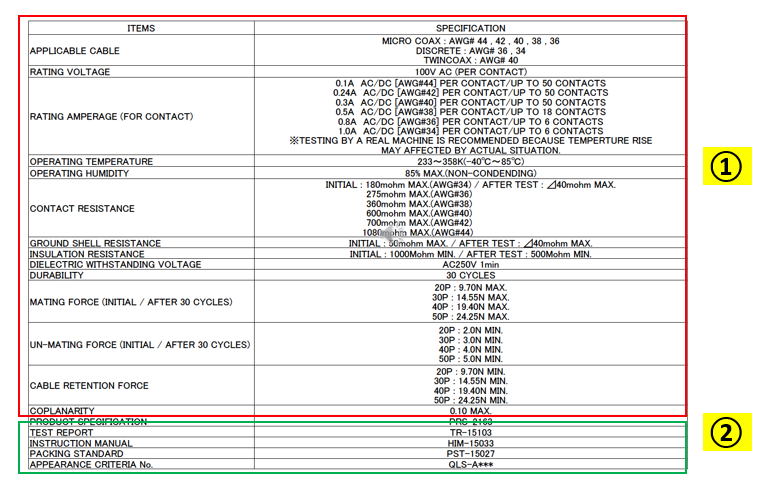
In general, I-PEX also has another technical document called a product specification that lists the various electrical, mechanical, and environmental test conditions and specifications of the product. The product drawing specification table lists some of the items that are important or frequently referenced for user convenience.
1. Specification titles and data
2. Shows the file number of technical documents, which customers can refer to if they need more details (e.g., specifications, test reports, work instructions)
Footprint and Metal Mask Layout Page
Illustrates the recommended sizes and layouts of pads and steel mesh.
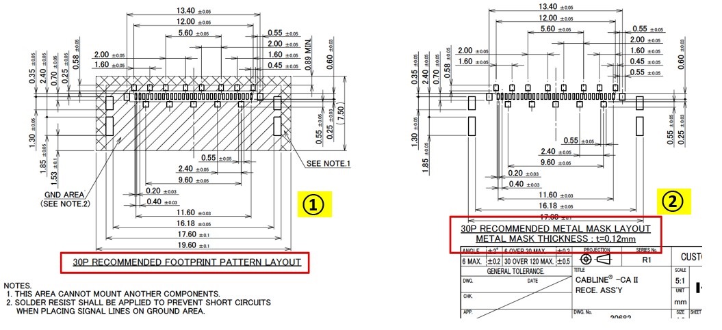
1. The recommended pad size and layout
2. The recommended hole size and layout of steel mesh (including hole size and mesh thickness)
Following this recommended design would help to reduce welding problems.
Reflow Condition Page
Shows the connector relative to the pad position and the recommended temperature curve for reflow.
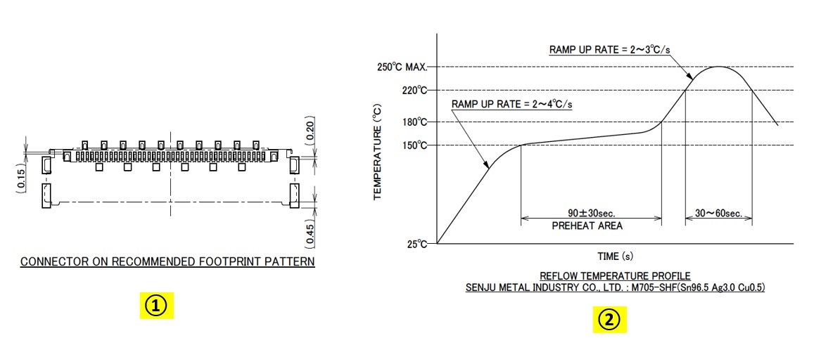
1. Shows the position of the connector on the recommended footprint pattern
2. Shows recommended furnace temperature curve for reflow
If the size or layout of the customer's footprint design or metal mask are different from the recommended design, the connector position to the footprint or recommended reflow condition would be different.
Packing Method of the Product Page
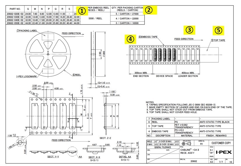
Generally, I-PEX SMT (Surface Mount Technology) products are packaged with tape and reel to facilitate the SMT production process. The size, material and packing quantity of each roll are shown.
1. Number of pieces per reel
2. Number of packages per carton
3. Feed direction of the reel
4. Tape and reel size and image
5. Cover tape image that is used for packing this product