

Robust Design with Integrated Locking Features
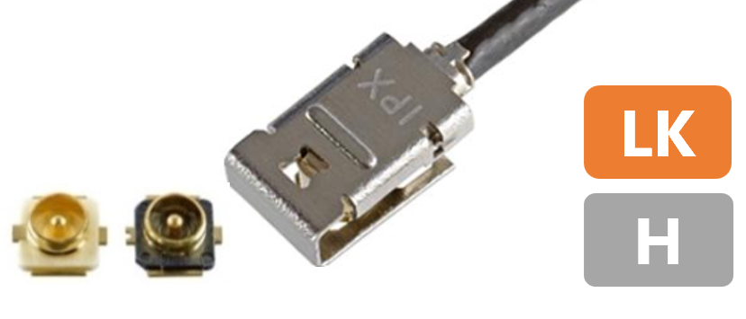
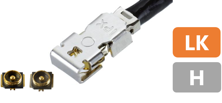
An integrated mechanical locking feature in antenna connectors plays a crucial role in ensuring reliable and stable connectivity in harsh operating environments such as those with high shock, vibration, or mechanical stress. It ensures secure, vibration-resistant, and stable electrical connections, reducing downtime, maintaining RF performance, and improving overall system reliability in demanding environments. The MHF® I LK and MHF® 4L LK enhance retention force by incorporating a locking mechanism into the standard MHF® I and MHF® 4L plugs. This innovation is particularly advantageous for applications where continuous connectivity is essential, including drones, fleet management, asset tracking, security, and personnel monitoring. With the introduction of locking functionality in two distinct sizes, MHF® I LK and MHF® 4L LK, design engineers can select options based on size and performance, thereby addressing various device and form factor challenges effectively.
Product Name |
MHF® I LK |
MHF® 4L LK |
|
Appearance |
|
|
|
Feature |
MHF® I with Mechanical lock |
MHF® 4L with Mechanical lock |
|
Part Number |
Plug |
20278-112R-** 20351-112R-37
|
20632-001R-37 |
Receptacle |
20279-001E-03 (3 pads) / 20441-001E-01 (4 pads) |
20449-001E-03 (MHF®4) / 20579-001E (MHF®4L) |
|
Mated Height |
2.9 mm max. |
2.0 mm max. |
|
SMT Size |
3.1 x 3.0 mm |
2.0 x 2.0 mm |
|
Cable Size
|
3.0 mm |
- |
- |
2.8 mm |
- |
- |
|
2.0 mm |
- |
- |
|
1.8 mm |
AWG 30 |
- |
|
1.37 mm |
AWG 30 |
AWG 30 |
|
1.32 mm |
AWG 32 |
- |
|
1.13 mm |
AWG 32 |
- |
|
0.95 mm |
- |
- |
|
0.81 mm |
AWG 36 |
- |
|
0.64 mm |
- |
- |
|
0.48 mm |
- |
- |
|
Frequency Range |
Up to 9 GHz |
Up to12 GHz
|
|
VSWR
|
DC to 3 GHz |
1.3 max. |
1.3 max. |
3 to 6 GHz |
1.5 max. |
1.4 max. |
|
6 to 9 GHz |
1.6 max.
|
1.5 max. |
|
9 to 12 GHz |
- |
1.6 max. |
|
Operating Temperature |
-40 to 90℃
|
-40 to 90℃ (233 to 363 K) |
|
(*) Please contact us for higher temperature connectors.
Graphs in Figure 1 below compare how the disengagement force increases with the integrated lock in MHF® I LK and MHF® 4L LK connectors as compared to MHF® I and MHF® 4L connectors. N represents a sample size of 5 connectors here.
| Disengagement force comparison | |

|

|
Figure 1. Comparison of Disengagement Force for MHF® I LK and MHF® I, MHF® 4L LK and MHF® 4L Connectors
Figure 2 shows the component placement prohibited area for MHF® 4L LK receptacle, mated with MHF® 4L plug harness. The figure also shows minimum recommended distance between adjacent mated MHF® 4L LK receptacles mated with MHF® 4L LK plug harness. The recommended minimum clearance between each MHF® 4L connector is also required to smoothly operate the I-PEX recommended locking / unlocking and mating / unmating Jig tool part number 91493-0001 also shown as a reference.


Jig Tool for MHF® 4L LK Connectors
In traditional snap-on or push-type connectors, vibration or movement can loosen the mating interface, leading to intermittent contact or complete disconnection. An Integrated lock secures the connector pair mechanically and ensures the connection remains intact even under continuous vibration or sudden mechanical shocks. This is critical in applications like automotive, industrial, and portable wireless systems. A locked interface also maintains consistent contact pressure between the connector’s mating surfaces, ensuring low insertion loss and high signal integrity up to 9 GHz in MHF® I LK and up to 12 GHz in MHF® 4L LK connectors. The locking feature minimizes micromotion and fretting corrosion, prolonging connector life and reducing the frequency of system maintenance. System designers can also achieve lightweight, vibration-proof antenna connections without sacrificing mechanical strength.
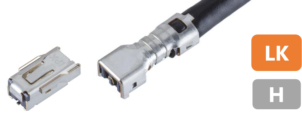
I-PEX also offers the MHF®-TI, designed for applications requiring even higher retention force. Its robust locking mechanism provides a clear tactile click to ensure secure mating and delivers a high retention force of 90 N minimum. This reliable locking system helps maintain a stable connection in environments exposed to vibration and shock, contributing to enhanced connection reliability.
Product Name |
MHF®-TI | |
Appearance |
|
|
Feature |
Robust design for automotive telematics antenna and camera sensors |
|
Part Number |
Plug |
20859-001R-01 |
Receptacle |
20860-001E-01 |
|
Mated Height |
3.65 mm max. |
|
SMT Size |
9.4 x 5.18 mm |
|
Cable Size
|
3.0 mm |
- |
2.8 mm |
- |
|
2.0 mm |
- |
|
1.8 mm |
- |
|
1.37 mm |
- |
|
1.32 mm |
- |
|
1.13 mm |
- |
|
0.95 mm |
- |
|
0.84 mm |
- |
|
0.81 mm |
- |
|
0.64 mm |
- |
|
0.48 mm |
- |
|
Frequency Range |
Up to 6 GHz |
|
VSWR
|
DC to 3 GHz |
1.5 max. |
0.3 to 3 GHz |
- | |
3 to 6 GHz |
1.5 max. |
|
6 to 9 GHz |
- |
|
9 to 12 GHz |
- |
|
12 to 15 GHz |
- |
|
Operating Temperature |
-40 to 105℃
|
|
Automotive Standards |
USCAR-2 * |
|
(*) Rev.6 - 5.4.6 (Vibration), 5.6.1 (Thermal Shock), 5.6.2 (Temp. & Humidity Cycle), 5.6.3 (High Temp. Exposure & Life) evaluation passed.
Features and Benefits of I-PEX RF Solutions
- 1. Compact Size and High Density
- 2. High Frequency and Data Rates
- 3. Superior EMC Performance
- 4. High Design Flexibility
- 5. Robust Design with Integrated Locking Features
- 6. Key Industry Standards
- 7. Consistent Performance with i-Fit® Technology
- 8. MHF® Switch Products for Antenna Testing
- 9. Available Accessories
- 10. PCB Stack Up Optimization Services
- 11. Signal Integrity Data
- 12. Signal Integrity Testing


