High Frequency and Data Rates for Modern High Speed Designs?
MHF Series connectors can support industry standard frequency bands from DC to 15 GHz enabling high speed wireless systems. Multiple MHF connectors can be used to successfully implement MIMO (Multiple Input, Multiple Output) systems that use multiple transmitting and receiving antennas to increase the capacity of wireless links providing benefits like increased capacity, higher data rates and better spectral efficiency enabling gigabit class connections. With ultra small size, mechanical locking and full EMI shielding, these connectors address unique challenges in implementation of MIMO functions in compact, portable 5G systems like limited space, isolation and coupling and signal interference. High speed wireless systems using MHF series antenna connectors offer various system level advantages like improved link budget and range, higher data throughput, enhanced signal integrity, reliable MIMO and beam forming performance etc.
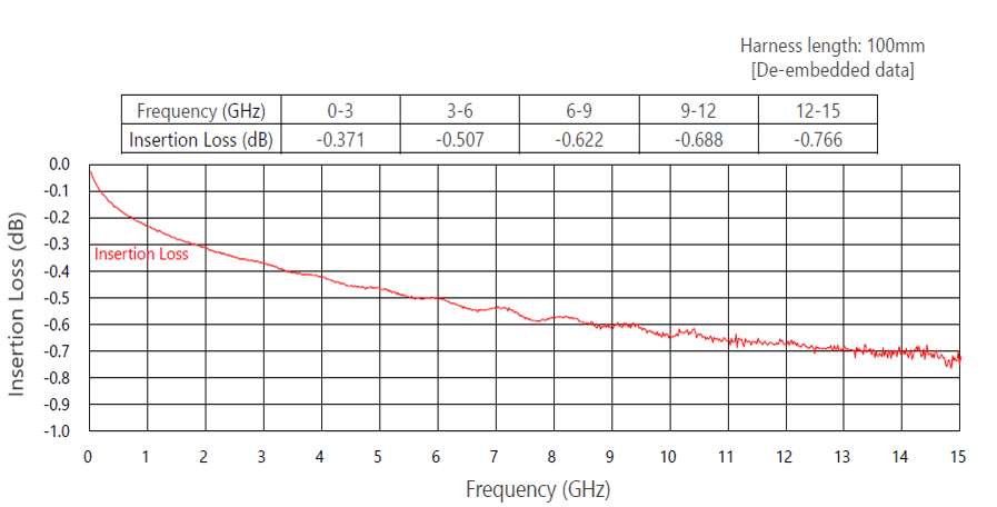
Insertion Loss and VSWR are some of the key signal integrity parameters that play a critical role in signal integrity and high data rates of wireless systems using MHF connectors. Unique design of MHF connectors ensures very low Insertion Loss and VSWR for both the Harness Assembly and Connector all across the frequency spectrum of DC to 15 GHz. Figure 1 below shows the variation in Insertion Loss of 100 mm long MHF® 4L Harness Assemblies using 1.13 mm coaxial cables across the frequency range of DC to 15 GHz.
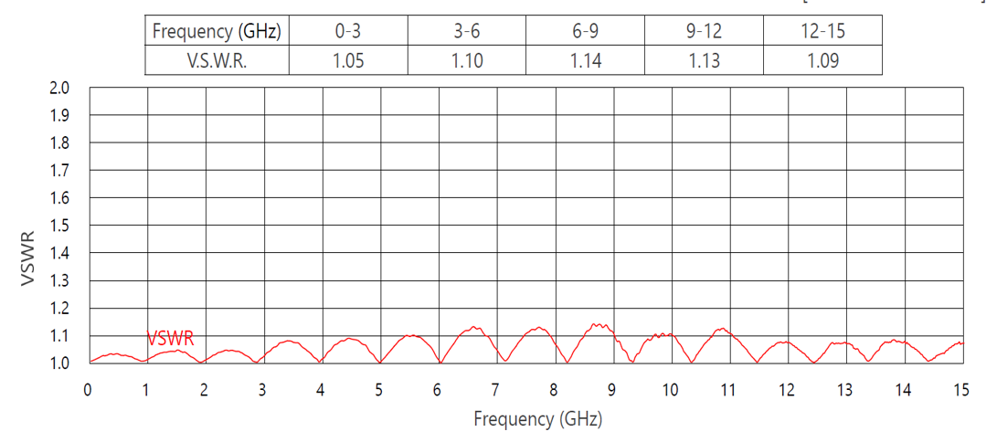
Similarly, the VSWR of MHF Harness Assemblies stays very low and fairly close to 1 across the complete operating frequency range of DC to 15 GHz as shown in the Figure 2. Low VSWR indicates excellent impedance matching between connectors and coaxial cables, resulting in better signal integrity with minimal signal reflections and distortion at high frequencies.
For more details, click to go to Product Matrix.
What is a RF Connector?
- 1. Compact Size and High Density of MHF Connectors for Portable Systems?
- 2. High Frequency and Data Rates for Modern High Speed Designs?
- 3. Superior EMC Performance with Integrated 360 degrees EMI ZenShielding?
- 4. Offers High Design Flexibility with Various Sizes and Multiple Cable Options?
- 5. Robust Design with Integrated Locking Features?
- 6. Key Industry Standards Supported?
- 7. Consistent Performance with i-Fit® Technology?
- 8. MHF Switch Products for Antenna Testing?
- 9. Available Accessories for MHF Connectors?
- 10. PCB Stack Up Optimization Services?