Compact Size and High Density of MHF Connectors for Portable Systems?
MHF Series connectors from I-PEX are ultra-miniature, low profile and light weight RF connectors that are typically used for Antenna connectivity in the latest smart phones, Tablet PCs and Notebook PCs etc. Smallest MHF connector takes up only 4 sq. mm of PCB area and availability of multiple stack up heights from 1 mm up to 3.65 mm typical provides design flexibility in RF systems with antennas for a variety of communication standards like Bluetooth, Wi-Fi and GSM etc. Connectors with integrated locking feature are useful in high vibration and shock environments and eliminates the need for separate external locks in design, saving board space and cost.
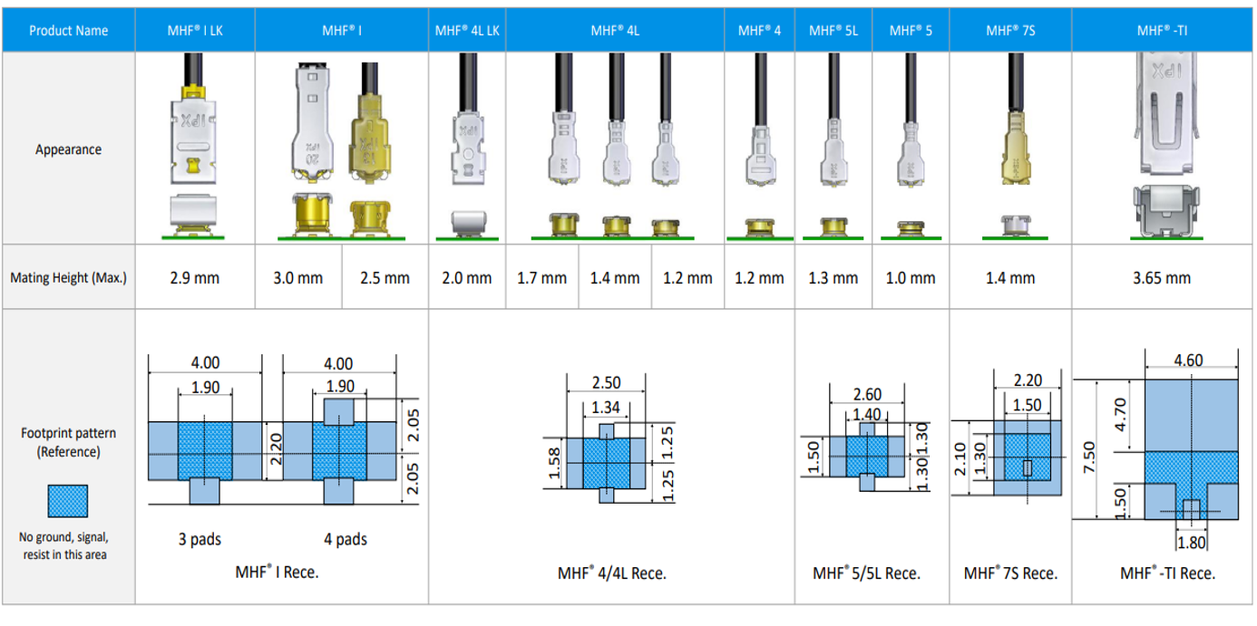
MHF connectors are available in various different sizes and profile heights as shown in the table below. The selection of different sizes, respective PCB footprints and mated heights makes them suitable for use in the latest Ultra-thin, high density, portable wireless devices without compromising the Signal Integrity performance. Often times, a PCB footprint on board is compatible with the multiple receptacles that can mate with more than one plug from the same MHF series. A good example is MHF® 4L series plugs and receptacles, where each of available three receptacles can be mounted on the same board side footprint offering choice of low to high mated profile heights and cable sizes in design.
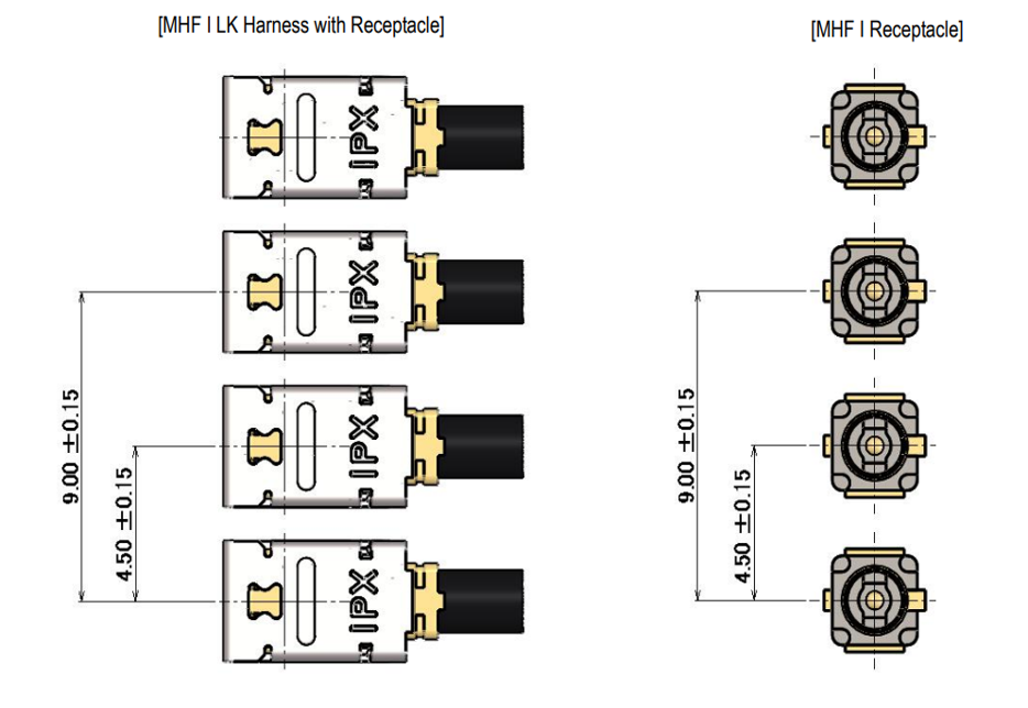
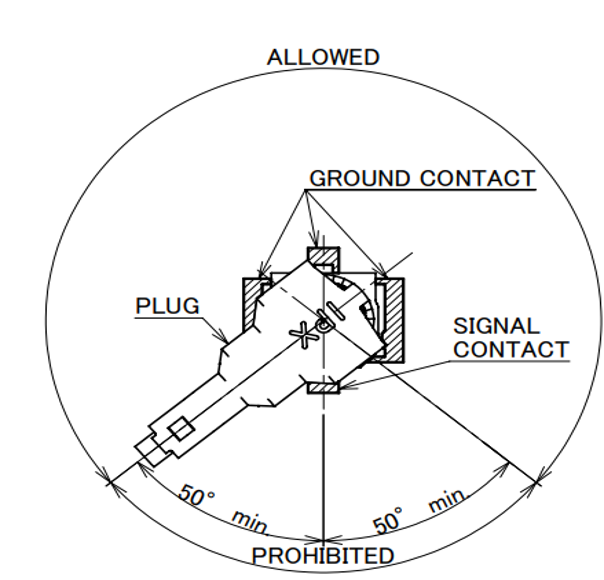
In high density designs with multiple RF lines and antennas, often times, there is a need to place multiple MHF connectors in close proximity to each other. Ultra small size of these MHF connectors allows them to be placed fairly close to each other. As an example, Figure 2 shows the recommended minimum distance between MHF® I receptacles to avid any interference in mating and unmating of plug assemblies since customers often use a hand tool to lock and unlock the plugs in installation and removal of plug cable assemblies on board. Similarly, Figure 3 shows that a second MHF® 5 receptacle (and mated plug) should not be placed with in 50 degrees from the center of signal contact to avoid any potential mutual interference between mated interconnect assemblies. Please contact us for recommended board lay outs and footprints of any other MHF series connectors in your design.
What is a RF Connector?
- 1. Compact Size and High Density of MHF Connectors for Portable Systems?
- 2. High Frequency and Data Rates for Modern High Speed Designs?
- 3. Superior EMC Performance with Integrated 360 degrees EMI ZenShielding?
- 4. Offers High Design Flexibility with Various Sizes and Multiple Cable Options?
- 5. Robust Design with Integrated Locking Features?
- 6. Key Industry Standards Supported?
- 7. Consistent Performance with i-Fit® Technology?
- 8. MHF Switch Products for Antenna Testing?
- 9. Available Accessories for MHF Connectors?
- 10. PCB Stack Up Optimization Services?