What Is a Micro-coaxial Cable Harness and Why Do You Need It?
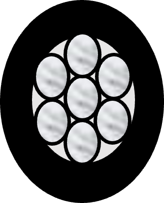
High frequency signals are more sensitive to electromagnetic interference (EMI) from near by communication sources like antennas, high speed board traces and transcievers on PCBs. By using micro-coaxial cables, these high speed signals are well shielded from noise and signal integrity of data is preserved. A micro-coaxial cable includes a center conductor for signal transmission that is surrounded by dielectric core for insulaion. There is outer metallic jacket with multiple strands for ground return current followed by PVC type jacket for additional insulation. In certain applications, power signals can also be transmitted by using the center conductor of micro-coaxial cable for DC supply and outer shield for DC return. In this case, the systems components can be shielded from noise emissions as a result of DC supply switching. Various sizes of micro-coaxial cables are available to use with I-PEX connectors based on required signal integrity performance in system.
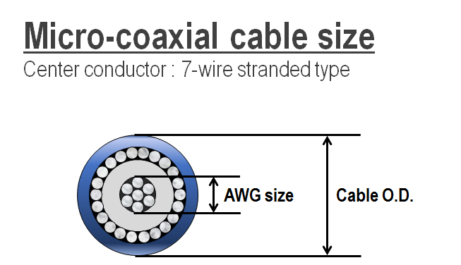
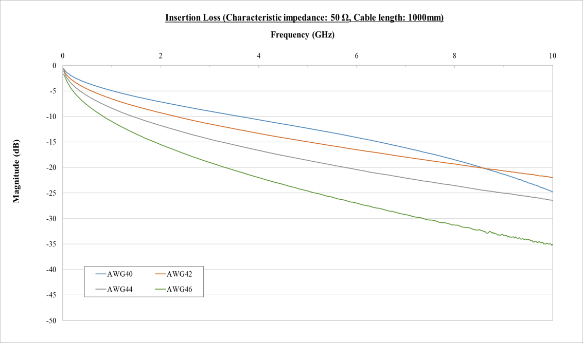
Various sizes of micro-coaxial cables are available to use with I-PEX connectors based on required signal integrity performance in system as shown below. Insertion Loss performance of various guages of 50 Ohms micro-coaxial cables is also shown below for reference.
|
AWG |
Center Conductor |
Cable outer Diameter (O.D.) (mm) |
|
|
Characteristic impedance |
|||
|
45Ω |
50Ω |
||
|
#30 |
0.3 |
1.04 |
1.16 |
|
#32 |
0.24 |
0.82 |
0.90 |
|
#34 |
0.19 |
0.67 |
0.73 |
|
#36 |
0.15 |
0.49 |
0.55 |
|
#38 |
0.12 |
0.39 |
0.46 |
|
#40 |
0.09 |
0.33 |
0.37 |
|
#42 |
0.075 |
0.29 |
0.33 |
|
#44 |
0.060 |
0.24 |
0.26 |
|
#46 |
0.048 |
0.22 |
0.24 |
Note : Reference only (Cable size varies depending on the types of cable.)
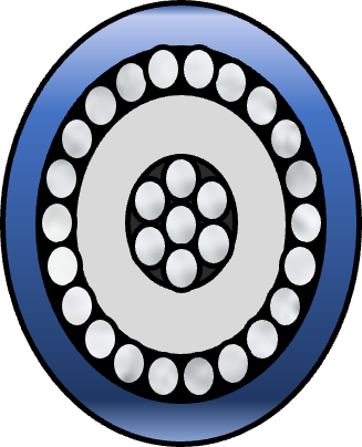
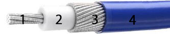
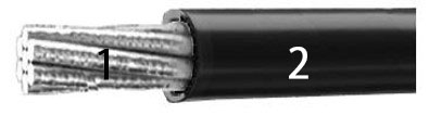
Discrete cables can also be used in high speed cable harnesses alongwith the micro-coaxial cables. Typically discrete cables are used for power delivery. Construction of a micro-coaxial and discrete cable is shown in the Figure 1 below. Table 1. shows current rating per pin for different sizes of center conductor both in micro-coaxial and discrete cables.
Micro-coaxial cable |
Discrete cable |
||
 |
 |
 |
 |
| 1. Center conductor 2. Insulator 3. Outer conductor (Shield) 4. Jacket |
1. Center conductor 2. Jacket | ||
Figure 1. Construction of Micro-Coaxial and Discrete Cables
| AWG | Current(A/pin) |
| #46 | 0.10 to 0.15 |
| #44 | 0.10 to 0.19 |
| #42 | 0.20 to 0.35 |
| #40 | 0.25 to 0.35 |
| #38 | 0.5 |
| #36 | 0.35 to 0.80 |
| #34 | 1 |
| #32 | 1 |
Table 1. Current Rating of Center Conductor
Diamter of center conductor in both micro-coaxial and discrete cables determines how much current can be carried by the cable. For example a micro-coaxial cable with 36AWG center conductor can carry currents up to 0.8A with out over heating. When it comes to current carrying ability, there is no difference between micro-coaxial and discrete cables. A CABLINE® harness is shown in Figure 2 with both micro-coaxial and discrete cables, note there is a blank pin between discrete and micro-coaxial cables to accomodate the ground bar.
↓One blank pin
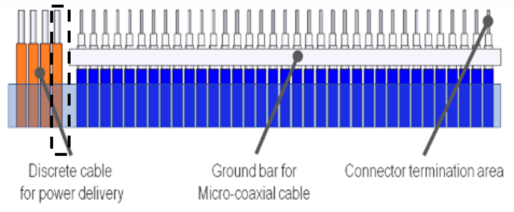
Note one blank pin
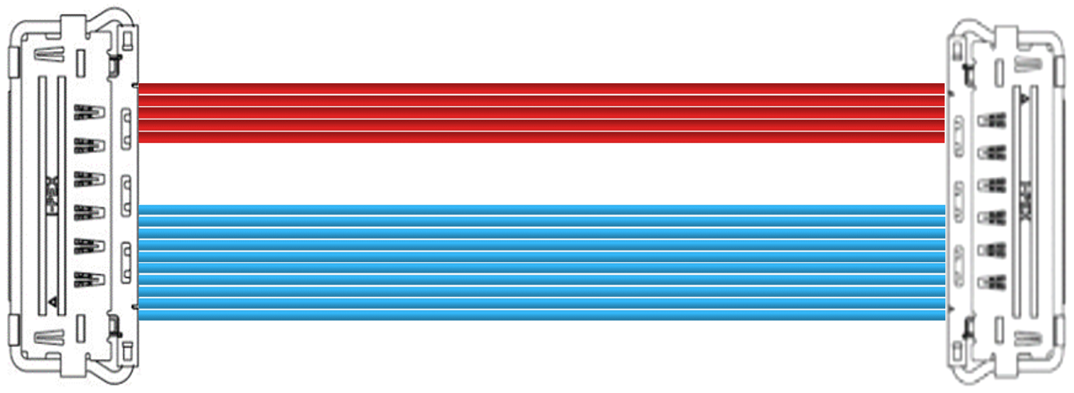
Figure 2. CABLINE® harness with micro-coaxial and discrete cables
Both shielded and unshielded connectors with optional mechanical lock are available for micro-coaxial harness assemblies. Low speed signals traveling on the PCB traces in designs with components that are placed relatively away from each other can use the connectors with out EMI shield since there is little interference between the signals. However, for higher frequency signals in relatively smaller, compact designs fully shielded connectors with ZenShield® and optional mechanical locking feature are offered for reliable connectivity. These connectors are used to connect digital signals between boards by the differential signal transmission method using micro-coaxial cables. To perform appropriate signal transmission, the center conductor which transmits the signal, needs to be connected to the signal circuit on the board via the contacts of the connector. The outer conductor of the cable needs to be electrically connected on the board via metal parts of the connector referred to as the shell. The electrical connection of the outer conductor to board through the connector shell is called "grounding". Learn about History of Micro-Coaxial Connectors here
