Pin Out
Depending on the signal pin out, lay out and routing of board traces, the pin assignments can be different on each connector in the harness assembly. Two different types of pin out configurations are offered in I-PEX High Speed Harness Assemblies i.e. 1-N type straight pin out and 1-1 type mirror pin out configurations for routing and placement flexibility in designs.
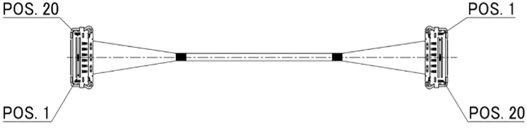
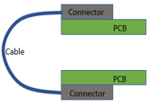
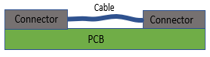
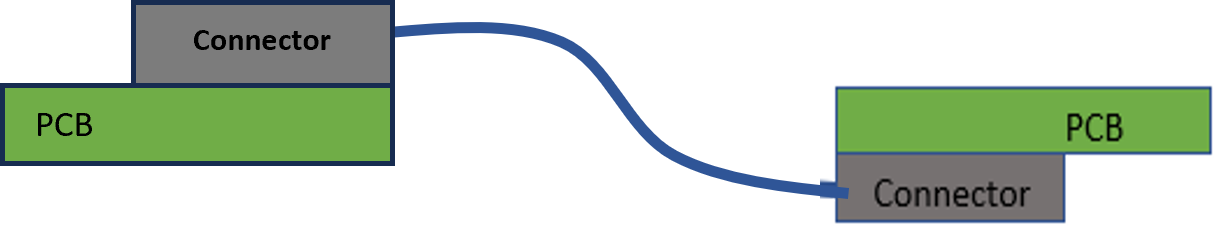
For example pin 1 on connector at one end of harness is connected to pin N of the connector on the other side of harness. In such a configuration, each Micro-coaxial cable is kept straight while connecting the two pins on on each side to avoid any crossing of cables with each other in the harness assembly. This placement is ahieved by rotating the PCB/ connector lead frame by 180 degrees relative to the other side in the harness. 1-N configuration of Harness Assemblies is useful in board designs where two components with Mirror Pin Out relative to each other must be connected in either a board to board or chip to chip on the same board design as shown below, without ruting the signals on various different layers or by using multiple Vias to cross the signals.
In the case of 1-N, Pos.1 of the one-side connects to Pos.N of the other one
|
|
 |
| Connector 1 | Connector 2 | |
| Pin Assignment | N | 1 |
| N-1 | 2 | |
| ・ | ・ | |
| ・ | ・ | |
| 2 | N-1 | |
| 1 | N |
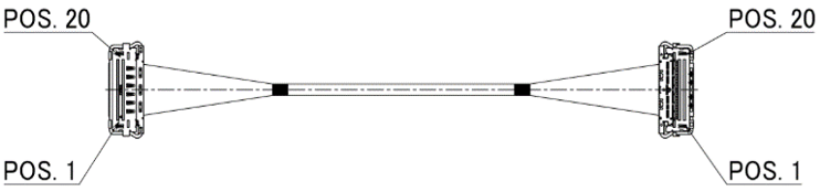
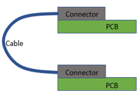
However, in 1-1 pin out configuration, pin 1 on connector at one end of harness is connected to pin 1 of the connector on the other side of harness. 1-1 configuration of Harness Assemblies is useful in board designs where two components either on the same board or on different boards with the same Pin Out relative to each other must be connected. A 1-1 pin out harness assembly is shown in the Figure 2 below:
In the case of 1-1, Pos.1 of the one-side connects to Pos.1 of the other one.
|
|
Placement image |
| Connector 1 | Connector 2 | |
| Pin Assignment | N | N |
| N-1 | N-1 | |
| ・ | ・ | |
| ・ | ・ | |
| 2 | 2 | |
| 1 | 1 |