Maximum Operating Frequency
Maximum operating frequency determines how fast and how much of the data can be transmitted in a high speed interface of communication system. Newer modulation techniques like PAM4 can send the data at the rate of 4 times the fundamental frequency offering a faster communication at the same base frequency.
CABLINE® series of products can support maximum frequency of 16GHz and data rates up to 64Gbps using PAM4 signalling. USB, eDP, Display Port and PCIe are some of the commonly supported proctocols.
With ever increasing data rates in new applications like high definition video streaming, internet of things and machine learning etc, there is a need to use high performance interconnect medium that is both low loss and high density to allow high fidelity data transmission with low latency. Specified max operating frequnecy of an interconnect determines the maximum data rate in an interface at which the there is no significant loss of data and system Bit Error Rate is minimal for reliable data communication at all times.
A coaxial cable includes a center conductor that is insulated and single or double shielded by construction. Most of the high speed data communication in both Enterprise and Portable consumer electronics uses differential data signals. When used for differential signals, coaxial cable provides an advantage of balanced signaling, rejecting common mode noise and restricts the electric and magnetic fields to inside of the coaxial cable, with little leakage outside the shield as shown in the figure 1 below.
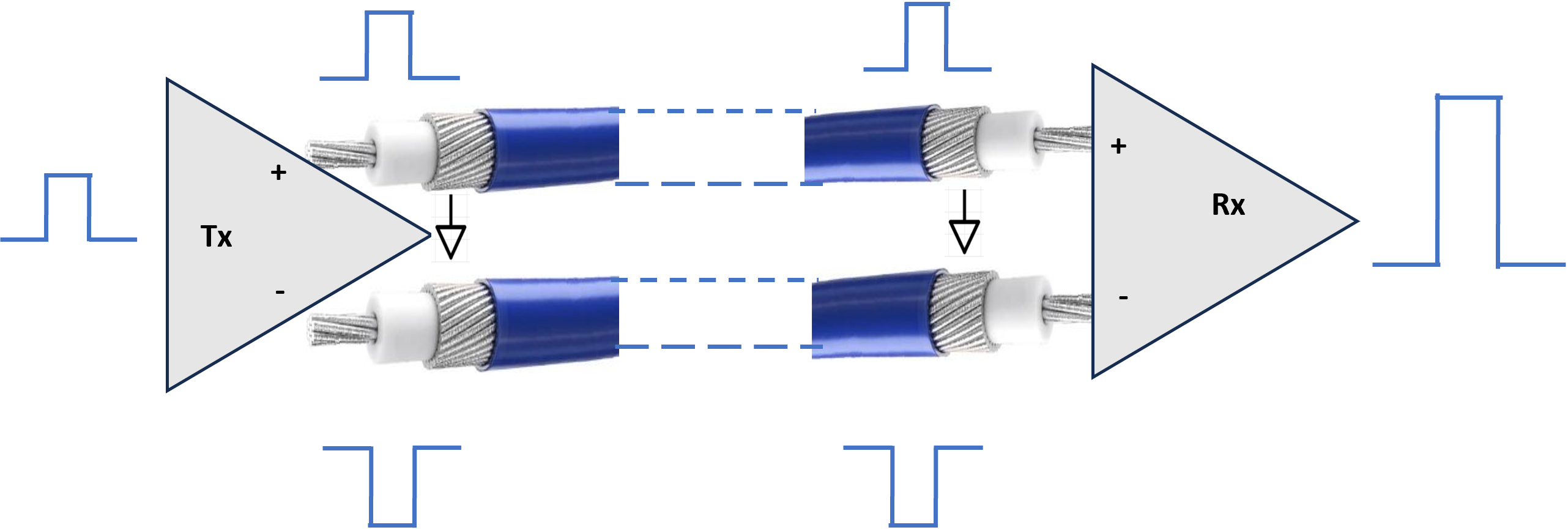
Further, electric and magnetic fields outside the cable are largely kept from interfering with signals inside the cable, if unequal currents are filtered out at the receiving end of the line This property makes coaxial cable a good choice both for carrying weak signals that cannot tolerate interference from the environment, and for stronger electrical signals that must not be allowed to radiate or couple into adjacent structures or circuits. This property also helps to minimize the cross talk between high speed signals in a compact system with many electronic components in a tight space.
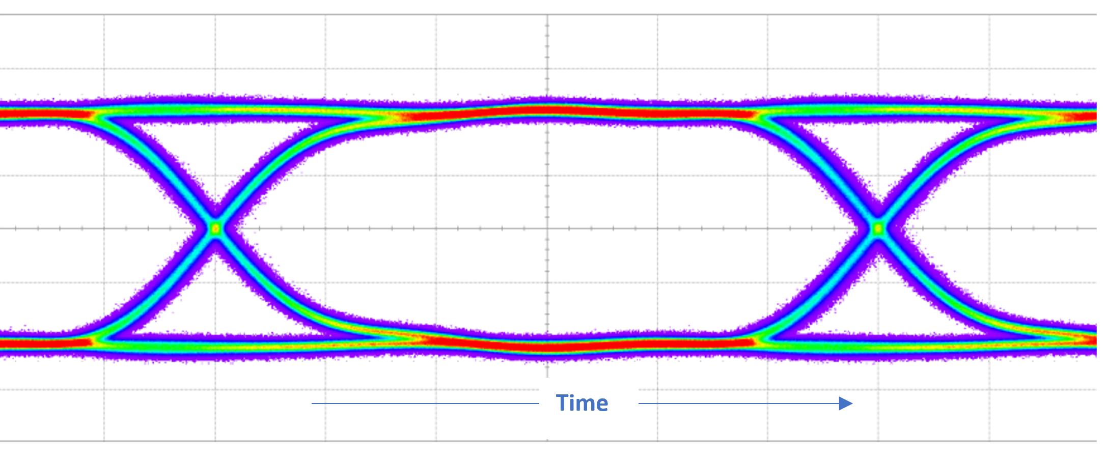
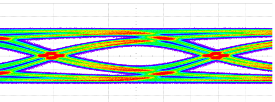
Impedance Matching in a Micro-coaxial Cable Assembly means that all of the components of a coaxial system including the connectors, cables and any interposer PCBs should have the same impedance to avoid internal reflections at connections between components. Such reflections may cause signal attenuation. They introduce standing waves, which increase losses and affect the signal integrty. This effect is specified as Voltage Standing Wave Ratio in data sheets . Impedance mismatch and high losses results in closed Signal Eye in high speed signal transmission leading to high Bit Error Rate and data loss on receiving end. For this reason, it becomes even more important to use a high performance, low loss cable interconnect with well matched impedance so that the high speed signals can be transmitted with high fidelity.
|
|
|
|