Design Consideration, Tips & Techniques for 5G Connector Solutions
The deployment of 5G networks, along with their connected devices, will demand more from current connector structures. This investment in connector technology, for high-volume manufacturing, will have to be balanced between performance, size, and cost to thrive in the market.
For multi-gigahertz applications, the need to isolate internal and external sources of electromagnetic interference (EMI) is uniquely challenging for 5G applications. Take a 5G mobile phone, for example. It contains multiple subsystems, (GPS, Wi-Fi-, Cellular sub-6 GHz and mmWave 5G), that need to work in concert to minimize antenna de-sense problems and ensure overall sub-system interoperability. The 5G Phone’s mmWave subsystem, which is designed for efficient mmWave radiation, must also be located adjacent to sensitive CPU core and passive antennas. This causes electromagnetic compatibility (EMC) nightmares. There are many solutions that exist to mitigate these concerns. However, these solutions tend to be CNC machined solutions with larger and heavily shielded coax structures. Enabling 5G devices for consumers requires a careful balance of performance, size, and cost. 5G UE devices must push the limits of miniaturization while producing maximum performance to enable these next gen devices. This trend shows no sign of slowing; just as EMC issues show no sign of becoming less complicated.
Microstrip and stripline miniature coaxial connectors combined with cable grounding & wire management solutions represent a collection of progressive EMI solutions. Small, shielded, and inexpensive, these components play a key role in the successful product engineer’s strategy for system EMI compliance.
Industry standard procedures for engineering designs are: achieving performance targets; utilization of components that balance size and cost constraints only after performance targets are met. However, as frequencies continue their inevitable rise, EMI reduction and isolation becomes a critical “first thought” requirement at the project’s inception. This helps reduce EMI “band-aid” solutions after the fact. These “late fixes” also tend to be more expensive via material costs and increases in production takt time.
Fortunately, there are progressively effective solutions that aid reduction of EMI system emissions to acceptable levels.
The first of component choices, is a low-cost, microstrip version of a board-to-cable solution, (see Figure 1). It provides basic micro-coaxial connection to a PCB microstrip structure. Microstrip performance can be acceptable for certain RF designs and occupies only 2-metal layers on the PCB, thereby reducing PCB cost and thickness. For higher frequencies, however, it may not suppress EMI radiation sufficiently to pass compliance.
In cases where microstrip transmission lines are insufficient to meet EMI performance requirements, a 3-layer stripline transmission structure may need to be employed. In these cases, the low-profile, higher performing RF stripline connector (see Figure 6), is the go-to solution.
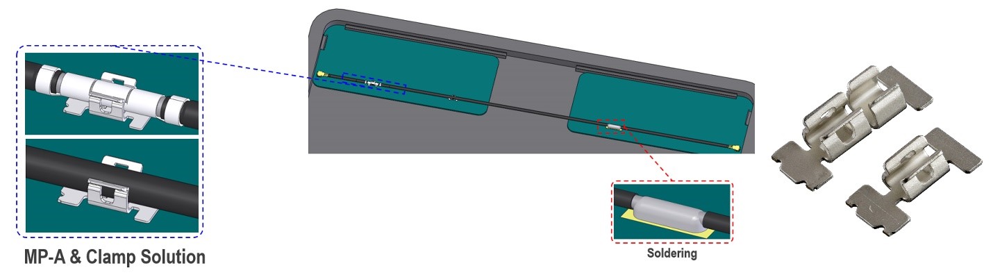
In high-performance environments, where additional EMI countermeasures must be employed, the addition of an SMT grounding clip (see Figure 3) can help. The clips provide suppression of EMI-induced current on the cable shield, as well as offering improved cable routing management using minimal PCB space. This is a good low-cost tool that greatly suppresses EMI emissions thereby minimizing the amount of PCB layout redesign.
The associated improvements in shielding effectiveness, from addition of the SMT Cable Ground clips, are readily apparent in a comparison of Figures 4 and 7.
The shielding performance of these following four cases are examined more closely using Ansys HFSS 3D EM Simulation:
Case 1 – Budget EMI Performance Needed, Microstrip Transmission Lines
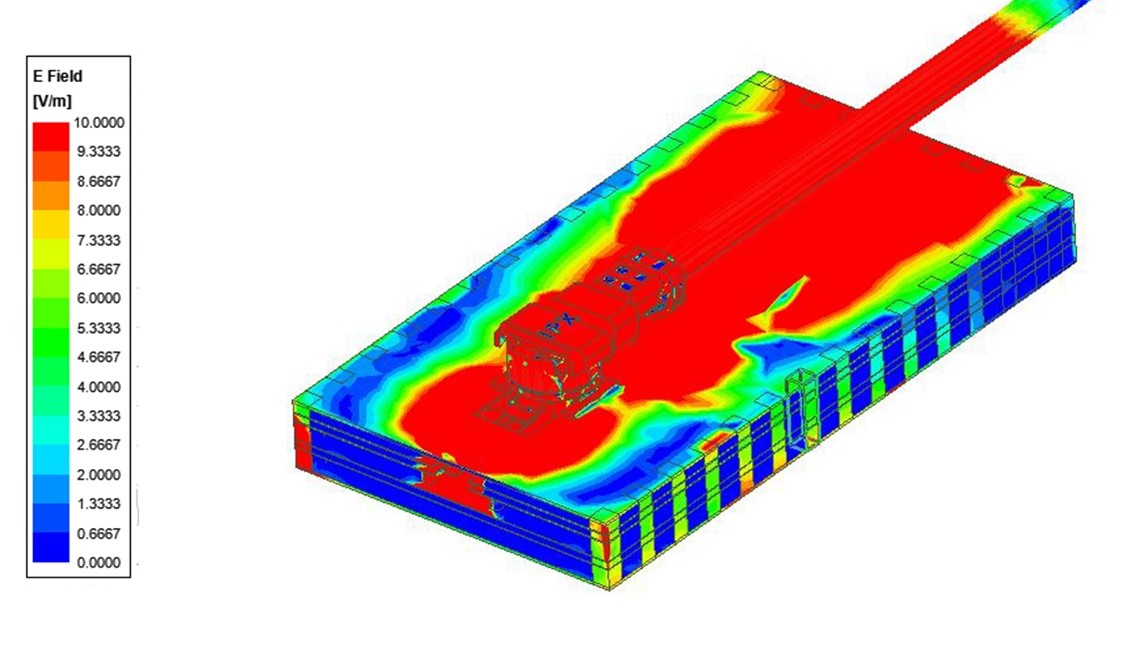
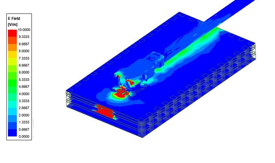
The microstrip transmission line case is setup with the microstrip RF connector and simulated in HFSS. As seen in Figure 2, the microstrip structure allows radiation to escape the guided wave structure.
Case 1b –RF Microstrip Connector with Additional SMT Ground Clip
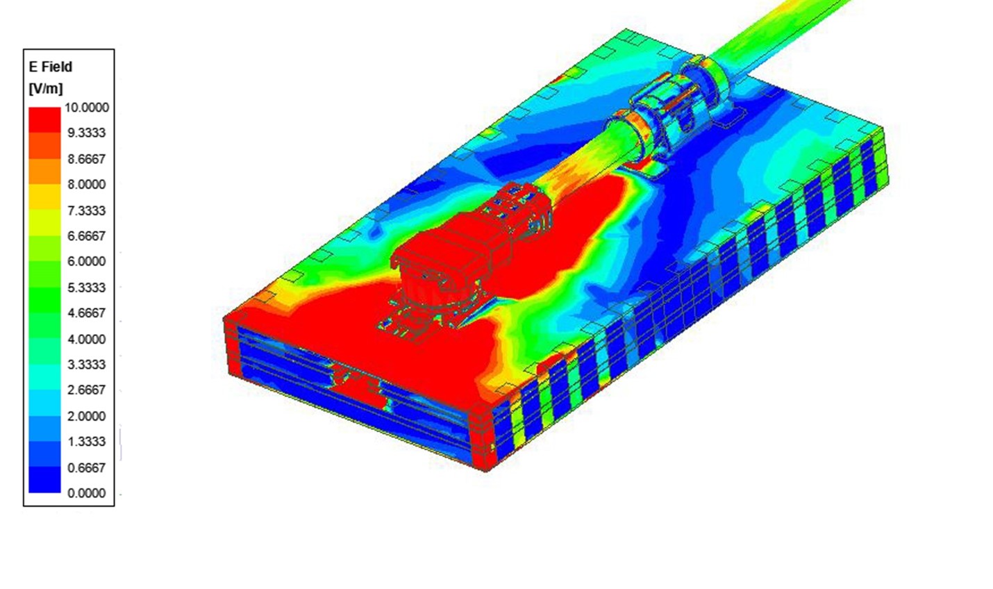
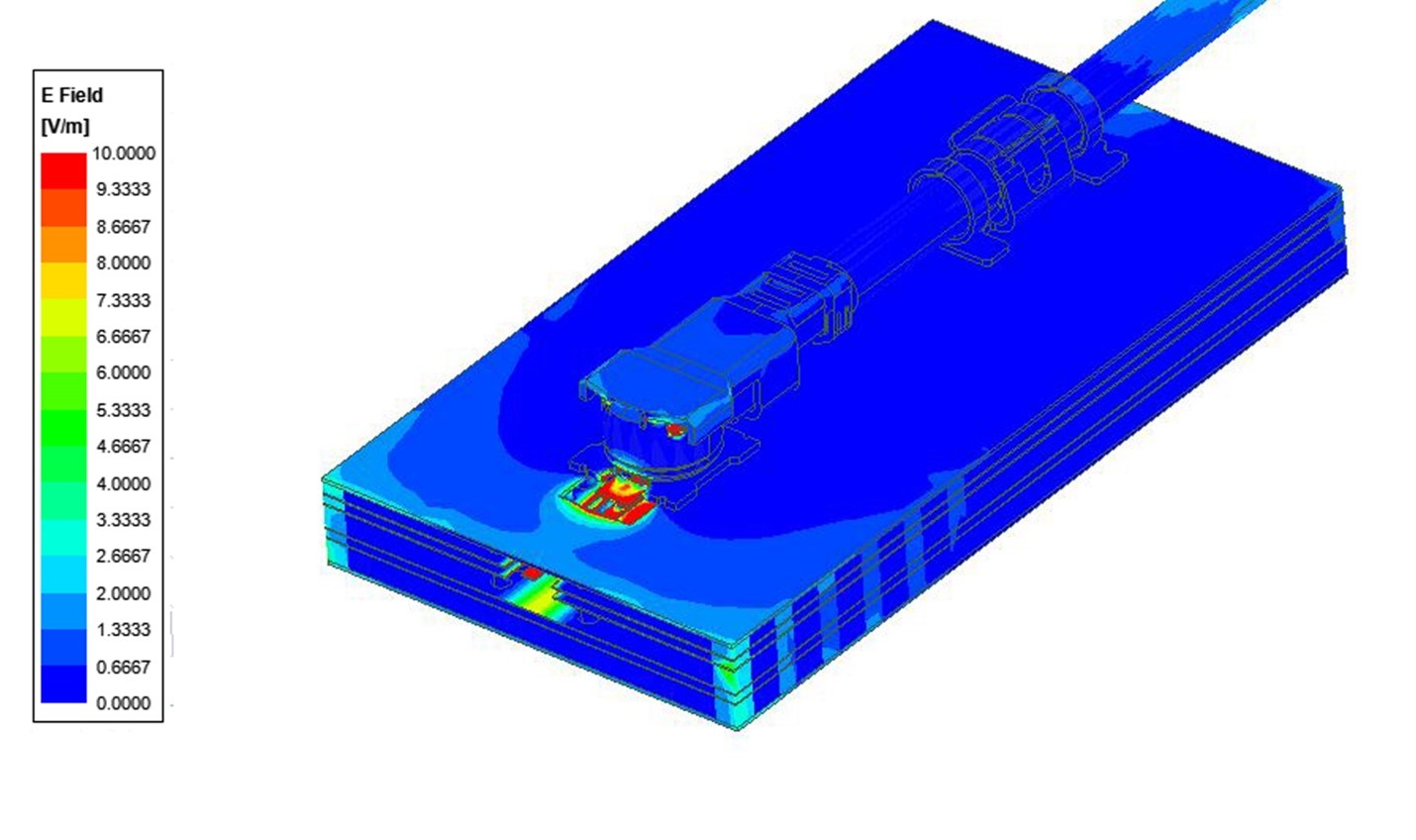
With the addition of the SMT ground clip, the EMI radiation is localized to the area around the launch point and significantly reduced along the length of the microstrip line (see Figure 4). It should also be pointed out that while this does not yield total shielding, it does not require extra ground layers and the associated cost of a new board spin.
Case 2 – Higher Level EMI Performance Needed, Stripline Transmission Lines and RF Stripline Connector Needed
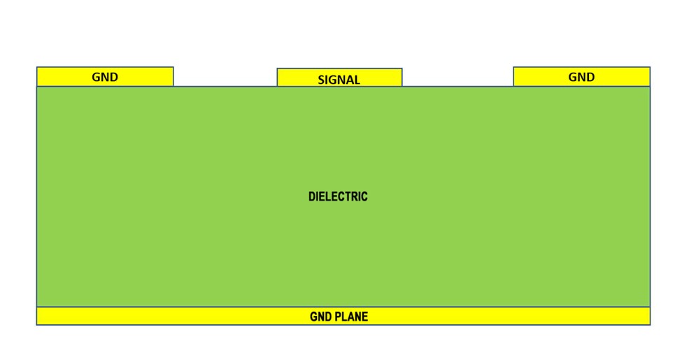
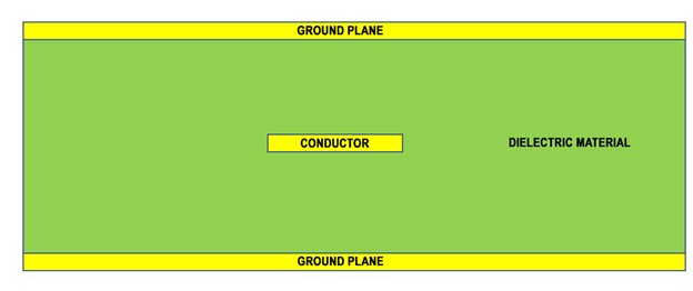
For robust premium value designs, 3-layer stripline transmission line structures are commonly used (see Figure 5). For these, a novel solution for stamped connectors is employed (see Figure 7). The signal conductor is completely contained within the boundaries defined by ground layers, on both sides of the signal layer, which provides the best shielding in a PCB design.
Case 2b –Stripline Transmission Lines and RF Stripline Connector with Additional SMT Grounding Clip Provides Highest Degree of EMI Suppression
For extremely sensitive systems requiring the highest EMI shielding suppression performance. The addition of the SMT grounding clip, further enhances the performance of the RF-shielded stripline-to micro-coaxial connector (see Figure 7).
Conclusion
Successive improvements in the EMI shielding effectiveness can be achieved by use of:
1. Microstrip RF Coaxial Connector, (see Figure 2)
2. Microstrip RF Coaxial Connector + SMT Cable Ground Clip, (see Figure 4)
3. Stripline RF Coaxial Connector, (see Figure 6)
4. Stripline RF Coaxial Connector + SMT Cable Ground Clip, (see Figure 7)
With the adoption of 5G devices, we have seen an increase in performance pressures for connector technology. The niche of stamped connector solutions has risen to the challenges posed by 5G: performance, space, and cost. This technology evolution will inspire novel solutions posed by 5G now and the foreseeable future.