

Signal Integrity Performance
Signal Integrity (SI) becomes one of the dominant design constraints once FPC/FFC interconnects are used for high-speed digital interfaces with the typical data rates of >1 Gbps and signal rise times of <500 ps. Planer and/or parallel traces of FPC/FFC type interconnects result in minimal shielding, moderate impedance control, high cross talk and low EMI immunity at such data rates, thereby making signal integrity performance even more critical for connectors used in such interconnects.
EVAFLEX® series connectors can be used with both Shielded and non-shielded FPCs and FFCs and are specified to operate up to 24 +Gbps with low insertion and return loss. Tight impedance control, integrated Ground contact pins, strict manufacturing tolerances for these connectors ensure excellent time domain reflectometry performance and open Signal Eye in high-speed signal transmission leading to minimal Bit Error Rate and high-fidelity data on receiving end.
In general, at high speeds of >1 Gbps, signal integrity performance of Shielded FPC/FFC is better than standard non-shielded FPC/FFC. Variations can be seen in Impedance with bending and manufacturing tolerances. Cross talk, insertion loss, return loss, signal jitter and propagation delay are some of the critical factors in signal integrity performance of FPC/FFC interconnects. Return Loss can be seen as the measure of reflected signal due to impedance mismatch and indicates how well energy is transmitted. Insertion loss is signal power lost as it travels through interconnect and is caused by conductor loss, dielectric loss and signal radiation in transmission medium.
Shielded FPC interconnects using EVAFLEX® series connectors using multiple Ground contacts, ensure high signal integrity by minimizing Insertion loss, Return Loss and EMI noise.
Figure 1 shows the return loss and insertion loss performance of 100 mm long shielded FPC with differential impedance of 85 Ohms when terminated to EVAFLEX® 5-HD connector for reference. Based on the loss performance, the EVAFLEX® 5-HD series connectors are specified for a maximum data rate of 24 Gbps per lane. However, the acceptable data rate may vary in different applications based on the design constraints of FPC/FFC used.
|
Measurement results |
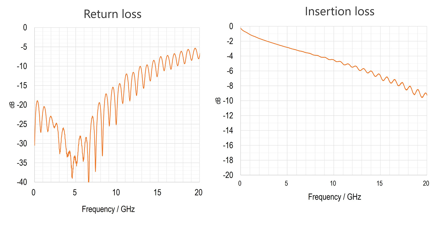 |
Figure 1. Insertion Loss and Return Loss Performance of EVAFLEX® 5-HD based FPC Interconnect
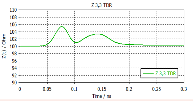
A Time Domain Reflectometry plot shows change in Impedance profile of complete interconnect including shielded FFC/FPC, Connector and board traces over time, when a high-speed signal with sharp input edge is travelling on the transmission channel. Figure 2 shows the simulated TDR plot of high frequency signals up to 30 GHz with the rise time of 25 ps over shielded FPC interconnect that uses EVAFLEX® 5-HD connectors.
The differential impedance in the connector region of interconnect stays consistent at target value of about 100 Ohms with minimal variations showing very well-matched uniform impedance of connector.
Eye Diagram provides composite visualization of signal quality over time. Key metrics of Eye Diagram are Eye Height ensuring required noise margin and Eye Width providing timing margin. Eye Diagrams are also often used to observe any signal jitter, which is basically variation in signal timing. Signal Jitter can be random or deterministic and reduces overall timing margin, leading to Bit error Rates in system.
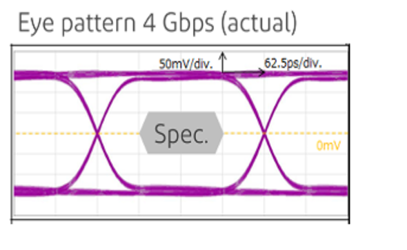
Figure 3 shows measured Eye pattern for shielded FFC interconnect with I-PEX EVAFLEX® 5-SE-G VT series connectors. Excellent signal integrity and timing margins are seen up to 4 Gbps data rates with defined rise and fall edge rates and minimal jitter.
Learn more: EVAFLEX® 5-SE-G VT


