Techniques for Mitigating Intrapair Skew-Induced EMI with Shielded Connectors
Introduction
The mediums over which electrical signals travel can either help or hurt the electromagnetic compatibility of a system. Common mediums include printed circuit board (PCB) traces, interconnects, and cables. In order to see how intrapair skew induces EMI, EMI must first be defined.
What is EMI?
EMI stands for electromagnetic interference. It is unwanted noise in an electrical net generated by an external source. EMI can take various paths from the source to the affected device. Two common paths are radiated interference and conducted interference. Radiated EMI occurs when an electrical device produces a radio frequency (RF) signal that is picked up and causes unwanted effects. Conducted EMI occurs when unintentional energy is carried out of the source via signal cables or PCB traces.
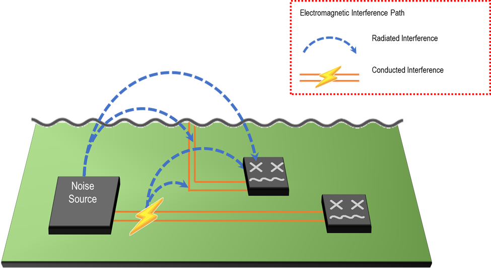
Common noise sources include antennas, RF chips, and power supplies. Adverse effects of EMI include failing regulatory emissions tests and affecting neighboring antenna sensitivity.
The Evolution of EMI Requirements
Over the past 40 years, EMI requirements have evolved. In 1985, Cray made the world's most powerful supercomputer. Today, that computing power resides in a smartphone. In the 1980s, system level shielding consisting of a metal case was sufficient for a typical computing system. Today, that computing system has shrunk to handheld size, the external cables have been cut, and radiating elements (antennas) have been intentionally added as features. As such, component-level shielding is now required to isolate radiating subsections from one another.
Cable Assemblies & EMI
As mentioned earlier, cable assemblies are a common medium for electrical signals in today’s electronic devices. In order to see how cable assemblies affect EMI, the components of the cable assembly need to be reviewed, namely the cable construction and the connectors on the ends.
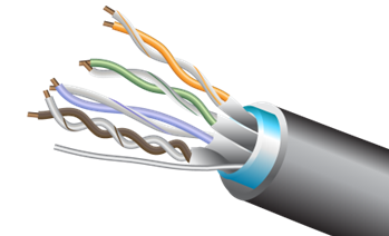
There are two common types of unshielded cables – discrete cable and twisted pair.
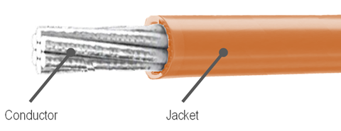
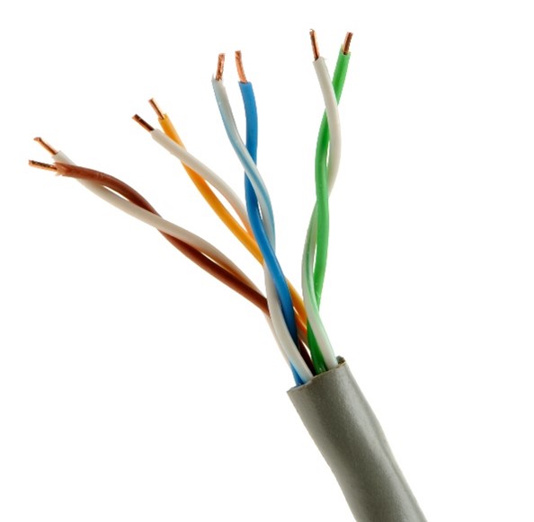
Since neither have shielding around the conductors, the EMI radiation is unhindered.
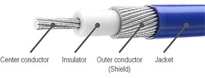
Shielded cables mitigate EMI by wrapping a shield around the conductors. Two common examples are micro-coaxial cable and shielded twisted pair.
Shielding the conductors helps with direct radiated emissions from the cable, but mismatches within a differential pair also exacerbate EMI. This mismatch causes intrapair skew.
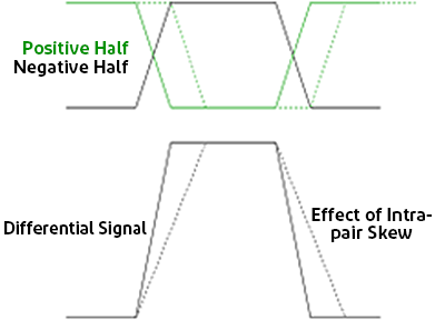
Intrapair Skew
Intrapair skew, or P/N skew, is the timing difference between the positive and negative signal lines within a differential pair. It is caused by mismatches in electrical length or unequal propagation delays.
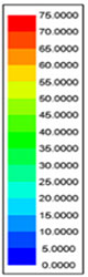
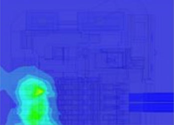
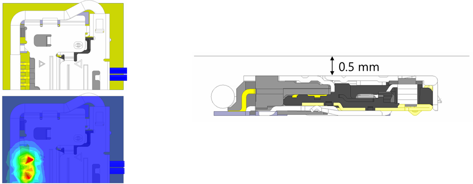
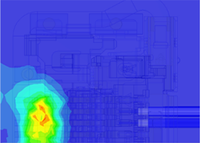
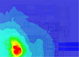
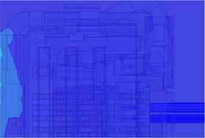
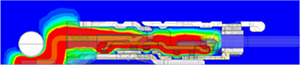
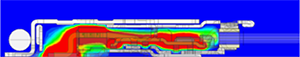
A cable assembly with a significant mismatch in P/N lengths generates larger electric fields (E-fields) than a cable assembly with matched differential pair lengths. Below is a comparison of simulated E-field plots of a cable assembly that uses micro-coaxial cables with an unshielded connector. The plot on the left has a differential pair with matched lengths, while the plot on the right has a mismatch of 4 mm within the pair. The length mismatch causes intrapair skew and results in a much larger E-field.
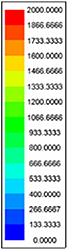
| E Field [V/m] |
Matched Length | Mismatched Length-4mm | |
|---|---|---|---|
| Cable assembly with micro-coaxial cable and an unshielded connector |
 |
 |
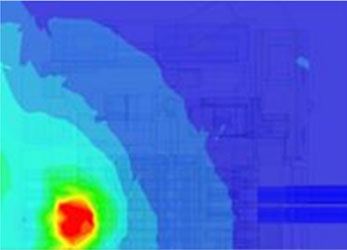 |
Figure 7. E-field of cable assembly with matched length vs. 4 mm mismatch
Shielded connectors help contain this E-field generation in order to mitigate EMI. However, not all connectors that have a shell or shield will work. The shield needs to completely surround the signal contacts in order to contain the E-fields. At I-PEX, a technology called ZenShield® is used to provide EMI shielding on a variety of different connector products.
Fully Shielded ZenShield® Connectors
A connector is only labeled with ZenShield® if it has the following three characteristics:
- The entire connector is covered with a 360-degree shield for both the plug and receptacle.
- The shield-to-shield interface between the plug and receptacle is connected at multiple points.
- The connector shield-to-board interface can be grounded at multiple points on the board.
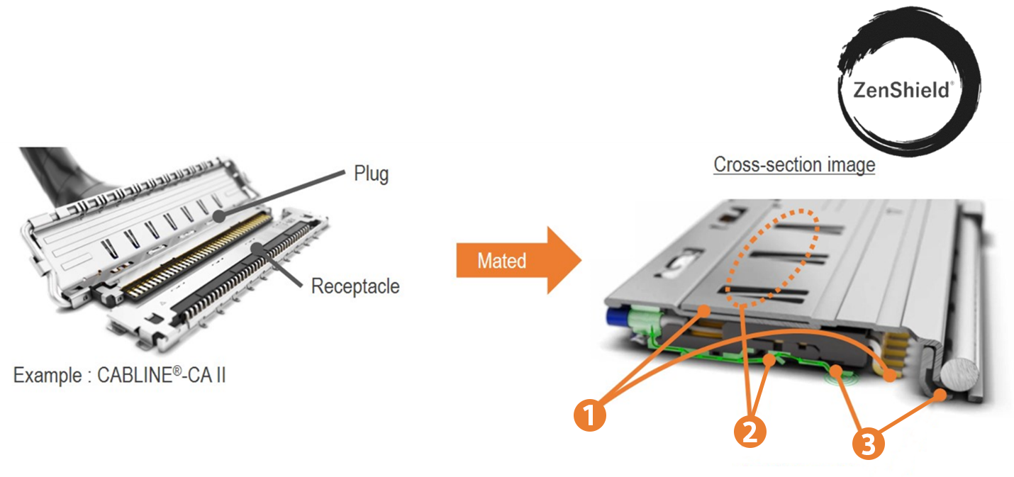
①The entire connector is covered by 360° shielding, for both the plug and receptacle
②The shield-to-shield interface between the plug and receptacle is effectively connected at multiple points
③The connector shield-to-board interface is properly grounded at multiple points on the board
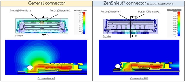
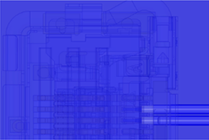
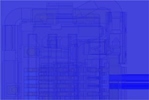
ZenShield® connectors block E-fields from leaking outside of the connector. As shown in the figure below, E-fields emanate freely from the unshielded connector on the left. The ZenShield® connector on the right blocks unwanted radiation from emanating outside of the connector.
Simulating Intrapair Skew-induced EMI
To show that ZenShield® connectors mitigate intrapair skew-induced EMI, an experiment was conducted with the following simulation conditions:
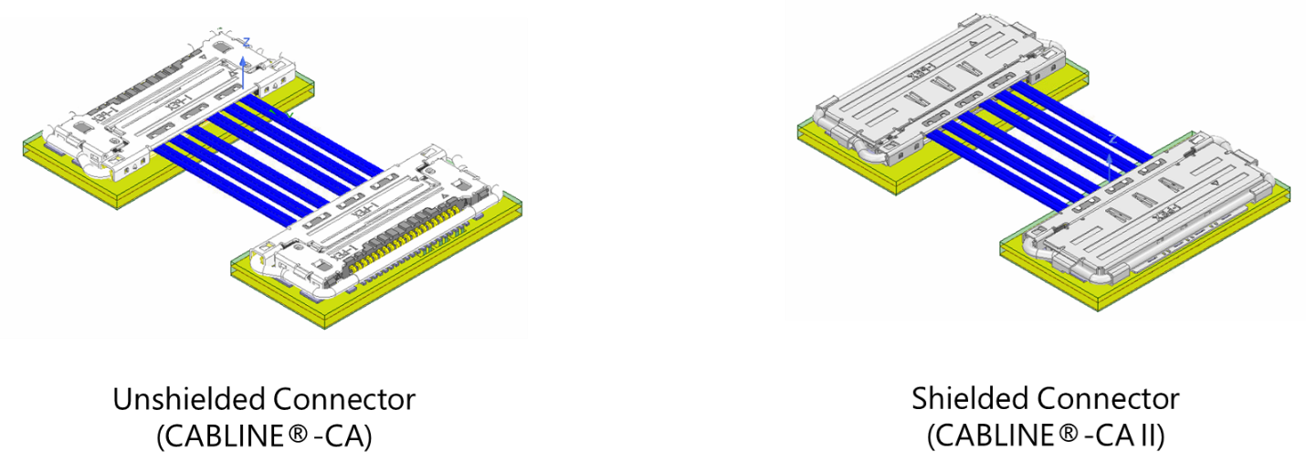
- One micro-coaxial cable assembly used unshielded connectors on both ends.
- One micro-coaxial cable assembly used shielded connectors on both ends.
- Both cable assemblies were simulated with the following length mismatches:
a. No P/N mismatch
b. Small P/N mismatch of 1 mm
c. Large P/N mismatch of 4 mm - Differential input data at 10 Gbps was used for all simulation conditions.
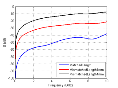
- The E-field plots were measured 0.5 mm above the connectors.
Based on the simulation results, the effective intrapair skew (EIPS) at 10 Gbps was 0.2 ps for condition 3(a) No P/N mismatch, 3.5 ps for condition 3(b) Small P/N mismatch of 1 mm, and 16.6 ps for condition 3(c) Large P/N mismatch of 4 mm.
| Condition | Skew (ps) |
|---|---|
| No P/N mismatch | 0.2 |
| Small P/N mismatch of 1 mm | 3.5 |
| Large P/N mismatch of 4 mm | 16.6 |
The mismatch was also evident in the differential-to-common mode conversion data. The larger the mismatch, the greater the mode conversion. This was expected as the differential pair is imbalanced.
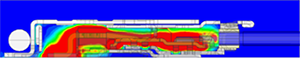
Comparing the E-field plots of the unshielded connector and the shielded connector shows the significant impact intrapair skew has on EMI, and the benefits of using a shielded connector.
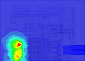
As the mismatch increases from left to right in the figures below, the E-field intensity can be seen increasing in the top row of the table, which represents the unshielded connector. However, the bottom row that has the results of the shielded connector does not show the same phenomenon. That is because the E-fields are contained within the ZenShield® connector. This can be seen in the side view of the connectors shown in Figure 14.
| E Field [V/m] |
Matched Length | Mismatched Length-1mm | Mismatched Length-4mm | |
|---|---|---|---|---|
| Unshielded Connector (CABLINE®-CA) |
 |
 |
 |
 |
| ZenShield® Connector (CABLINE®-CA II) |
 |
 |
 |
| E Field [V/m] |
Matched Length | Mismatched Length-1mm | Mismatched Length-4mm | |
|---|---|---|---|---|
| Unshielded Connector (CABLINE®-CA) |
 |
 |
 |
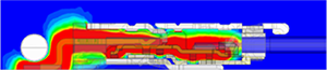 |
| ZenShield® Connector (CABLINE®-CA II) |
 |
 |
Conclusion
The tests described within this white paper show that ZenShield® connectors are an ideal solution to mitigate EMI that is induced by intrapair skew and provide additional margin for manufacturing and assembly tolerances for cable length mismatches.