How to Select a Micro-Coaxial Connector
Have you ever had a hard time choosing a micro-coaxial connector for high-speed transmission? --- There are many factors that can make it difficult to select a connector. In order to make the selection process easier, this article provides some examples of how to select the best connectors for your applications.

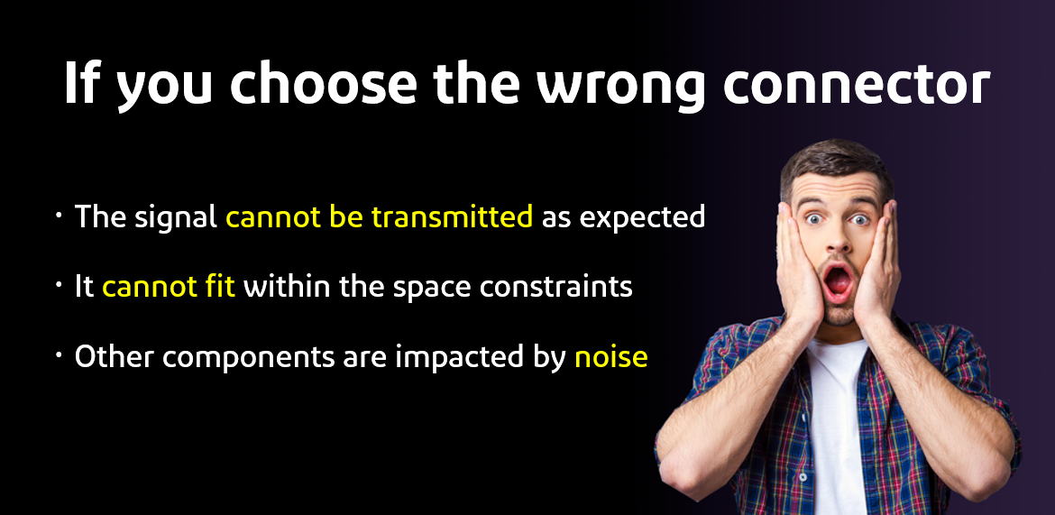
Have you ever thought to yourself, "I want to select a micro-coaxial connector, but I don't know how to decide"? The decision you make has a profound impact since the connector is a very important electronic component and will directly affect the device’s performance. Choosing the wrong connector may result in you being unable to reach your target performance.
So, are there any good methods for choosing a micro-coaxial connector?
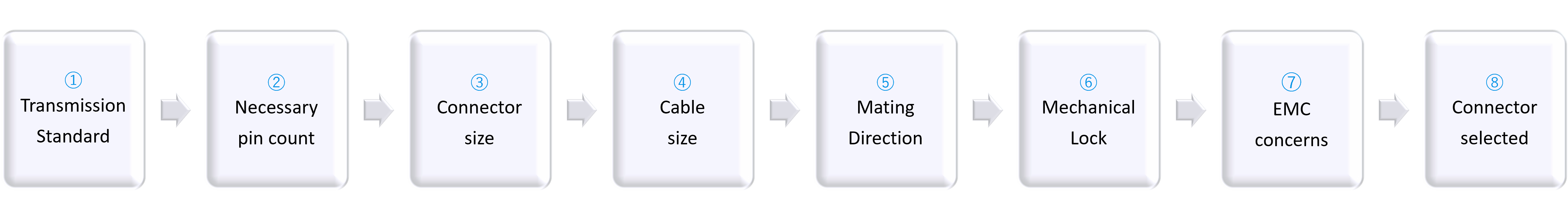
The selection process can go smoothly if you use the following steps:
Preparation --- First go to the I-PEX micro-coaxial connector selection tool on our website ( click here ).
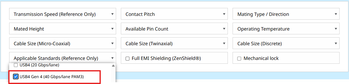
① Clarification of transmission standard
Different devices and components follow different transmission standards. Before choosing a connector, first choose the signal you want to transmit. The transmission speed is determined by the transmission standard. Here is an example of how to select the USB4 standard:
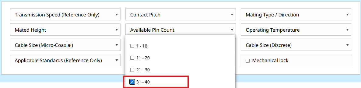
② Necessary pin count
The next step is to select the pin count required for the application. Choosing a large pin count requires the connector to be bigger, thereby using more space on the PCB. It also increases the cost.
Here is an example of how to select a 40-pin connector:
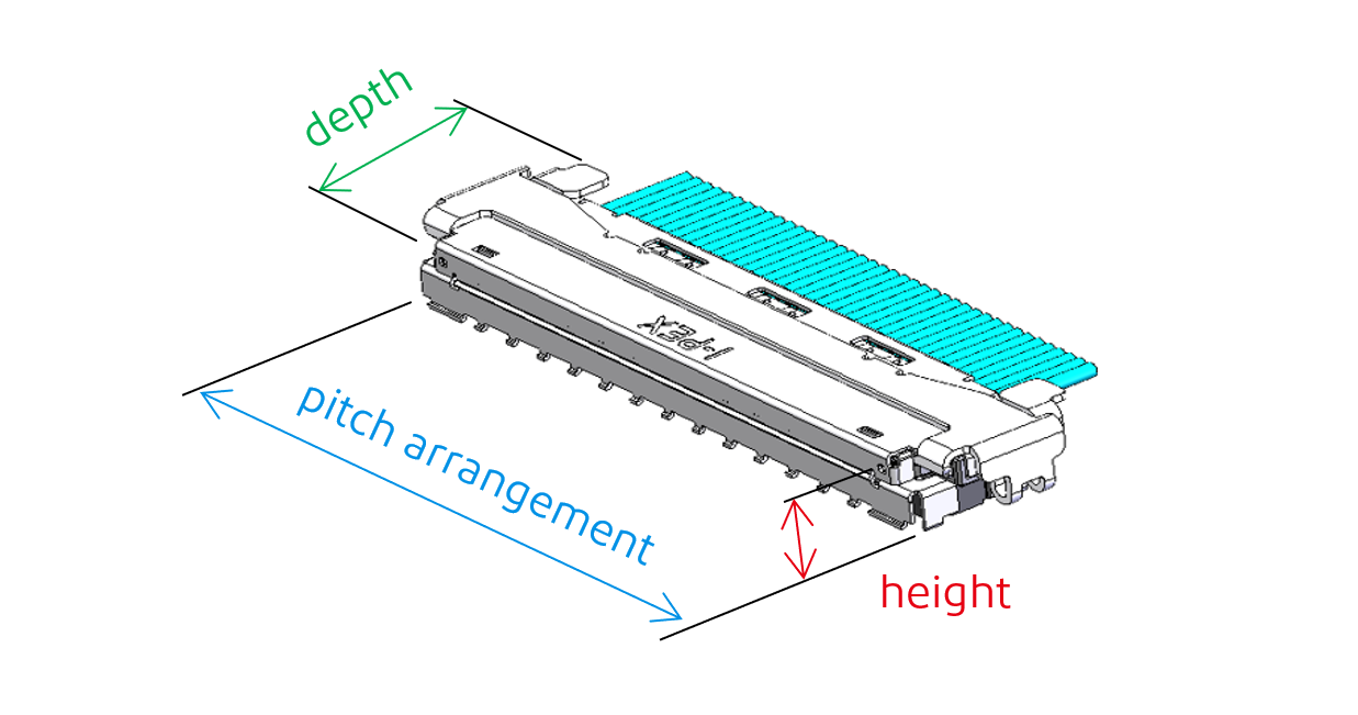
③ Clarification of connector size
The connector size is expressed in the height direction, pitch arrangement direction, and depth direction. Of these, the most common constraints are in the height and pitch dimensions.
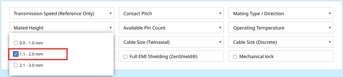
Why is the maximum mating dimension for connectors important?
Micro-coaxial connector receptacles are mounted on PCBs, then mated with a plug harness. If the mated height is too tall, it could possibly interfere with the device housing, resulting in the housing not fitting as planned.
Here is an example of how to select a maximum height of 1.2 mm:
What is pitch?
Pitch refers to the distance from the center of one contact pin to the center of the next contact pin.
Why is pitch important?
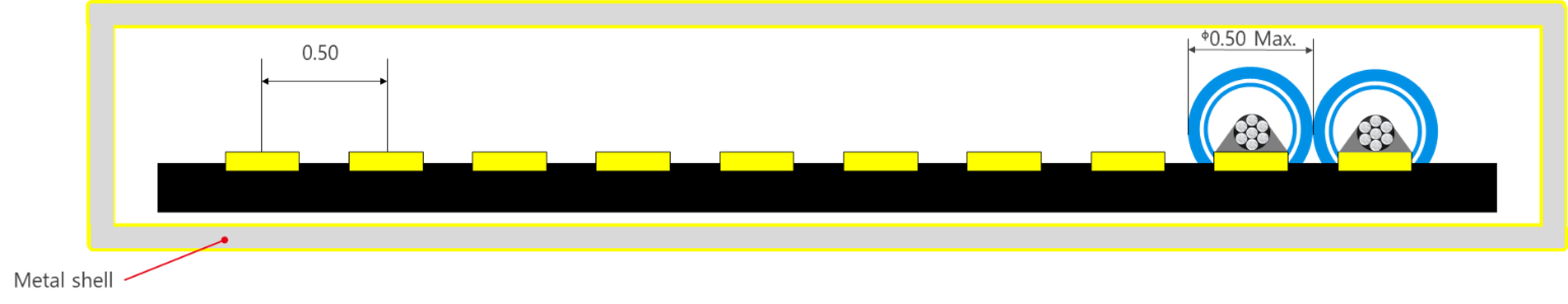
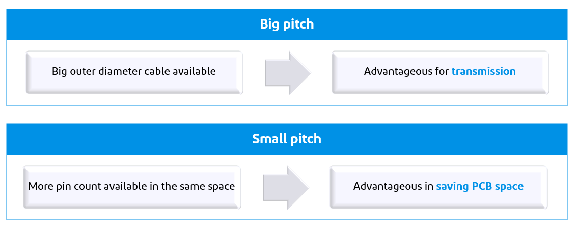
For micro-coaxial connectors, the pitch of the connector limits the maximum outer diameter of the cable that can be used.
Example 1: 0.5 mm pitch 10-pin connector, compatible cable outer diameter 0.5 mm Max.
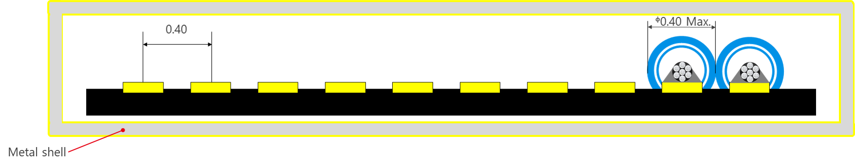
Example 2: 0.4 mm pitch 10-pin connector, compatible cable outer diameter 0.4 mm Max.
The larger the cable diameter, the lower the loss – resulting in better transmission properties. However, a larger cable diameter also occupies more space, leading to a thicker bundle.
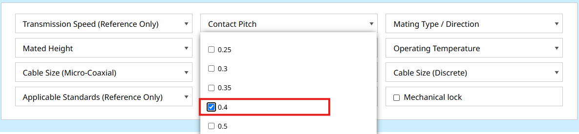
Here is an example of how to select a contact pitch of 0.4 mm:
④ Decide the cable size
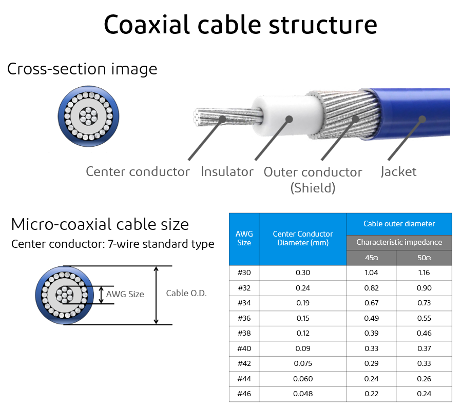
What is AWG(American Wire Gauge)?
As explained in the image below, AWG is a number expressed by the diameter of the center conductor. The greater the AWG number, the smaller the diameter.
Imagine running water through a pipe. The thicker the pipe, the more water can flow through it. The same applies to cables. The larger the diameter of the center conductor, the more current can flow through it. Conventional wisdom says that you should always use thicker cables. But, as mentioned previously, the cable size that can be used with a connector is also limited by the pitch of the connector.
What is cable impedance?
In the table of cable sizes above, the outer diameter of the cable changes based on the impedance. If we compare signal transmission to the flow of water through a pipe again, the smooth flow of water will be disturbed at the point where the diameter of the pipe changes suddenly.
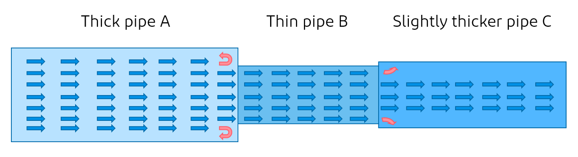
Similarly, if a signal passes through a path that is not impedance-matched, reflections will occur due to these disturbances. Impedance matching between the board, connector, and cable are required to transmit the signal with as few reflections as possible.
If the characteristic impedance is not matched (see image below), transmission loss will occur.
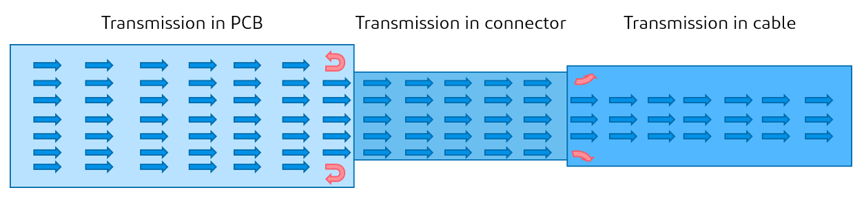
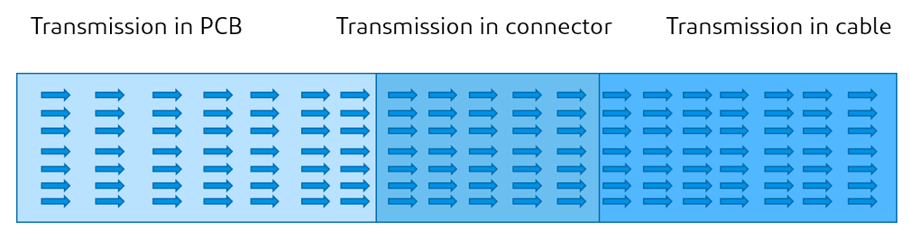
When the characteristic impedance is matched (see image below), the transmission loss can be reduced.
For many common applications, the impedance of the signal transmission path is specified as 50 Ω. However, it can vary, as the impedance is determined by each transmission standard organization. For example, the characteristic impedance of USB4 is specified as 42.5 Ω. In order to minimize the loss during high-speed transmission, it is important to select a cable that is close to the characteristic impedance required for the application.
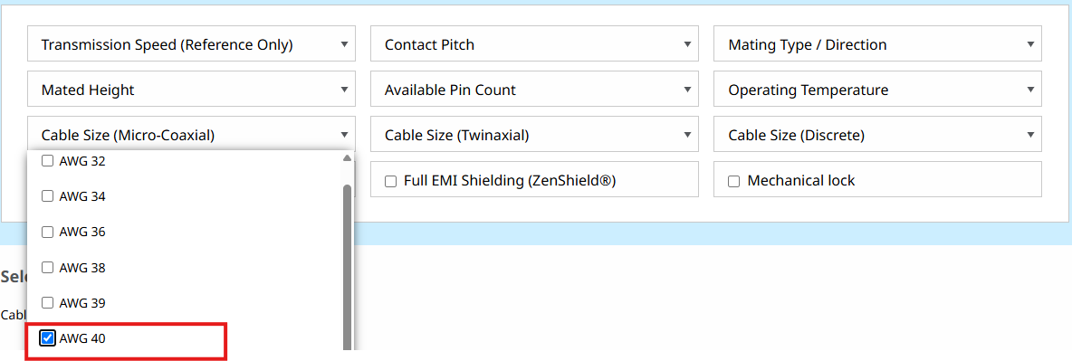
Here is an example of how to select AWG #40 for a micro-coaxial cable:
You can also choose the size of a discrete cable.
⑤ Determine the mating direction
The location of the connector on the board, the board size, and other conditions vary based on the customer and the application. The required mating direction of a connector also differs due to this reason.
Here is a related article about the mating direction of connectors: ( click here )
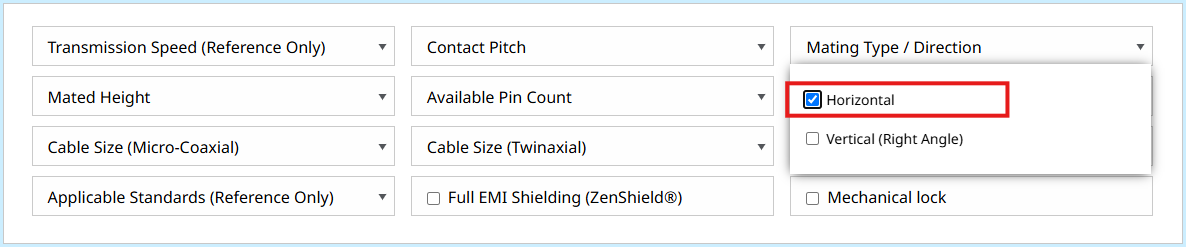
Here is an example of how to select a horizontal mating connector:
⑥Need for additional mechanical lock
When a secure connection is required in your application, products with a mechanical locking feature are available.
Learn more about our mechanical locking feature: (click here)
Example selection guide for connectors with a mechanical locking connector:
⑦ Need for additional EMC mitigation on the connector
What is EMC?
When the signal is being transmitted, it emits noise to its surroundings (EMI) and is concurrently impacted by noise from its surroundings (EMS). This noise generated by the signal can adversely affect the performance of peripheral devices. Likewise, when ambient noise interferes with the signal, its transmission is adversely affected.
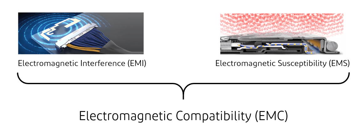
Our ZenShield® technology helps prevent ambient noise from affecting the signal in the connector, and also prevents the noise generated by the signal from affecting external components. This shielding technology gives you more freedom in the placement of other electronic components and contributes to the realization of high-density mounting, which is a trend in board mounting.
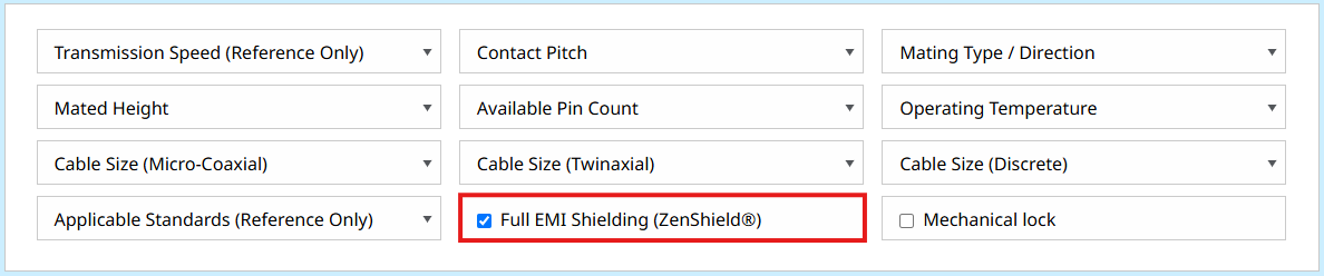
EMC Shielding (ZenShield®) example, assuming you have noise concerns.
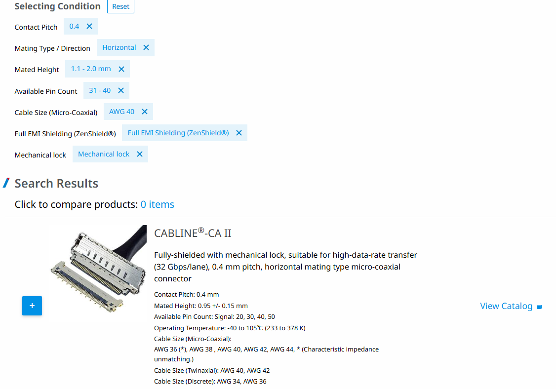
As a result, CABLINE®-CA II could be searched by following steps (1) to (7).
Did you choose the right connector in this order?

I-PEX is an expert in high-speed transmission connectors, and we design various types of connectors according to the customer's use case to achieve the best transmission performance. In addition to the above search methods, we have also prepared a product matrix table ( click here ) for the purpose of making it easier for you to find the right connector.