High Density
NOVASTACK® series connectors are available in pin counts ranging from 10 pins to 70 pins with pin pitch as small as 0.35 mm. These ultra small, light weight connectors facilitate modern, compact portable systems with out compromising the connectivity, where every square mm and every mg matters. Availability of multiple stack up heights from 0.6 mm up to 1.5 mm typical provides design flexibility in multi-board systems. Connectors with integrated power pins can handle currents up to 1 A / pin and eliminate the need for separate power connectors in design and save board space and cost.
At high frequencies of 1 Ghz and beyond, the high speed signals need to be fully shielded from the external signals near by and at the same time, these high speed signals must be contained well with in the connector to avoid any unwanted noise or interference in the board that can affect the signal integrity. Often termed as "Cowling", the unshielded connectors need an external removable metallic EMI shielding cover that takes up additional board space and ends up in higher BOM costs. At the same time, board designers need to design this external shielding cover and ensure the proper mounting at the optimal distance from the connector, a process that is time consuming and costly. With integrated 360 degrees EMI metallic shielding cover called ZenShield®, the NOVASTACK® series connectors save board space and cost, minimize design effort and reduce time to go to market. Availability of multiple pin count options provides design flexibility to the engineers, when it comes to board lay out and area. These connectors using FPCs allow fine-pitch connections, enabling a higher number of traces in a smaller area. Connectors with FPCs also enable tight and flexible interconnections between printed circuit boards (PCBs), reducing the need for bulky wiring or rigid connectors.
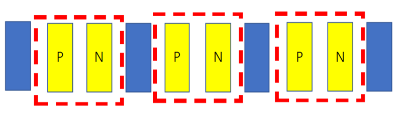
High density of connector can be seen as the availability of a large number of pins/ channels in a small, light weight form factor, while maintaining the excellent signal integrity of high speed data signals. As the pin count increases, the pin pitch decreases in order to keep the over all size of connector small. It is quite challenging to keep the cross talk between signals low with the tighter pin pitch since the effective distance between connector pins and signals is reduced. As the data rates increase beyond 10 Gbps or so, there is a need to use additional Ground pins between differential signal pairs to keep the adjacent channel cross talk low as shown in the figure 1 below. At such high data rates, most of the signal protocols like VESA DP UHBR 20 are more vulnerable to cross talk due to tighter pin pitch as compared to lower speed signals using Non Return to Zero (NRZ) type signals. Availability of multiple pin counts in NOVASTACK® series connectors allows the engineers to use the most optimal pin out for a specific signal protocol/ standard. Also, the High-density connections minimize the length of signal paths, reducing signal loss and improving transmission quality.
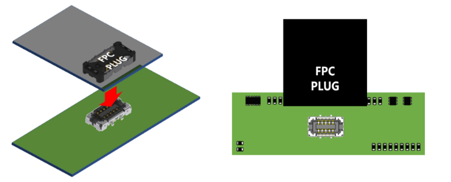
Most of board to board connectivity uses the Flexible Printed Circuits with the connectors on each board. Vertical mount configuration of NOVASTACK® connectors provides the flexibility to route high speed data signals, low speed control signals and power lines in many different layers and still terminate the FPC with the plug of NOVASTACK® series connector as compared to horizontal mating type ZIF connectors where the number of layers and thickness of FPC are limited by the specified gap in receptacle itself for the FPC. However, in case of board to board connectors using Flexible Printed Circuits, it may be difficult to visually align the plug on receptacle correctly since the FPC covers the entire plug and area around it and blocks the view of receptacle underneath as shown in the Figure 3 below:
For this reason, NOVASTACK® connectors are offered with alignment guides feature which allow the user to slide the plug over receptacle for proper mating alignment by using just fingertips with out any specialized tool as shown in the Figure 4 below:
| Guiding Aligned to proper position Push and lock | |
|
Plug
Receptacle |
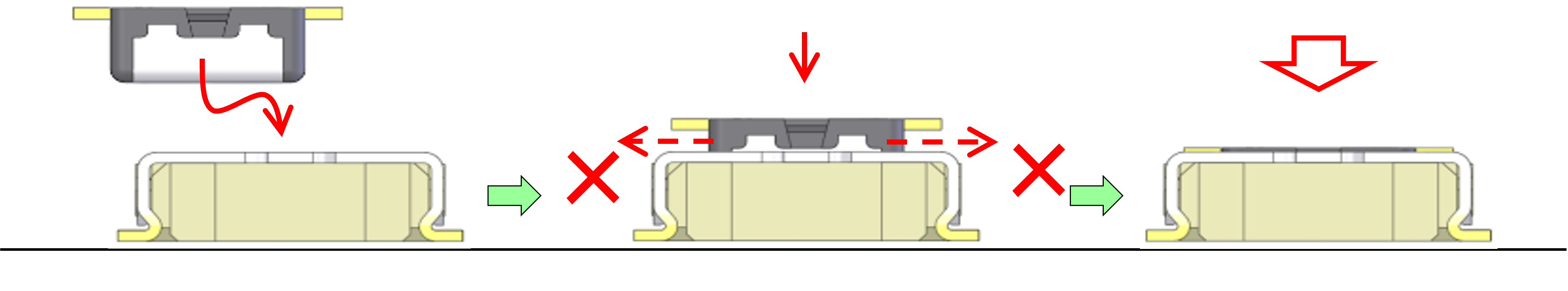
Mating position Mated condition |
Figure 4. Board to Board Connector Guide Function