

What is Wi-Fi 7?
The Difference Between Wi-Fi 6 and Wi-Fi 7
Wi-Fi 7 (IEEE 802.11be) builds on Wi-Fi 6 (IEEE 802.11ax) with wider channels, higher modulation, and Multi-Link Operation, which improves throughput, latency, and performance in crowded networks.
This article explores the key differences between the two standards, explains the underlying technologies such as QAM modulation, and highlights the design challenges and especially requirements set to connectors and cable harnesses associated with next-generation wireless systems.

Why Wi-Fi 7 Is Gaining Market Attention?
Wi-Fi 7 is not simply an incremental upgrade in speed; it introduces several key technologies that address limitations in previous generations and enable new use cases.
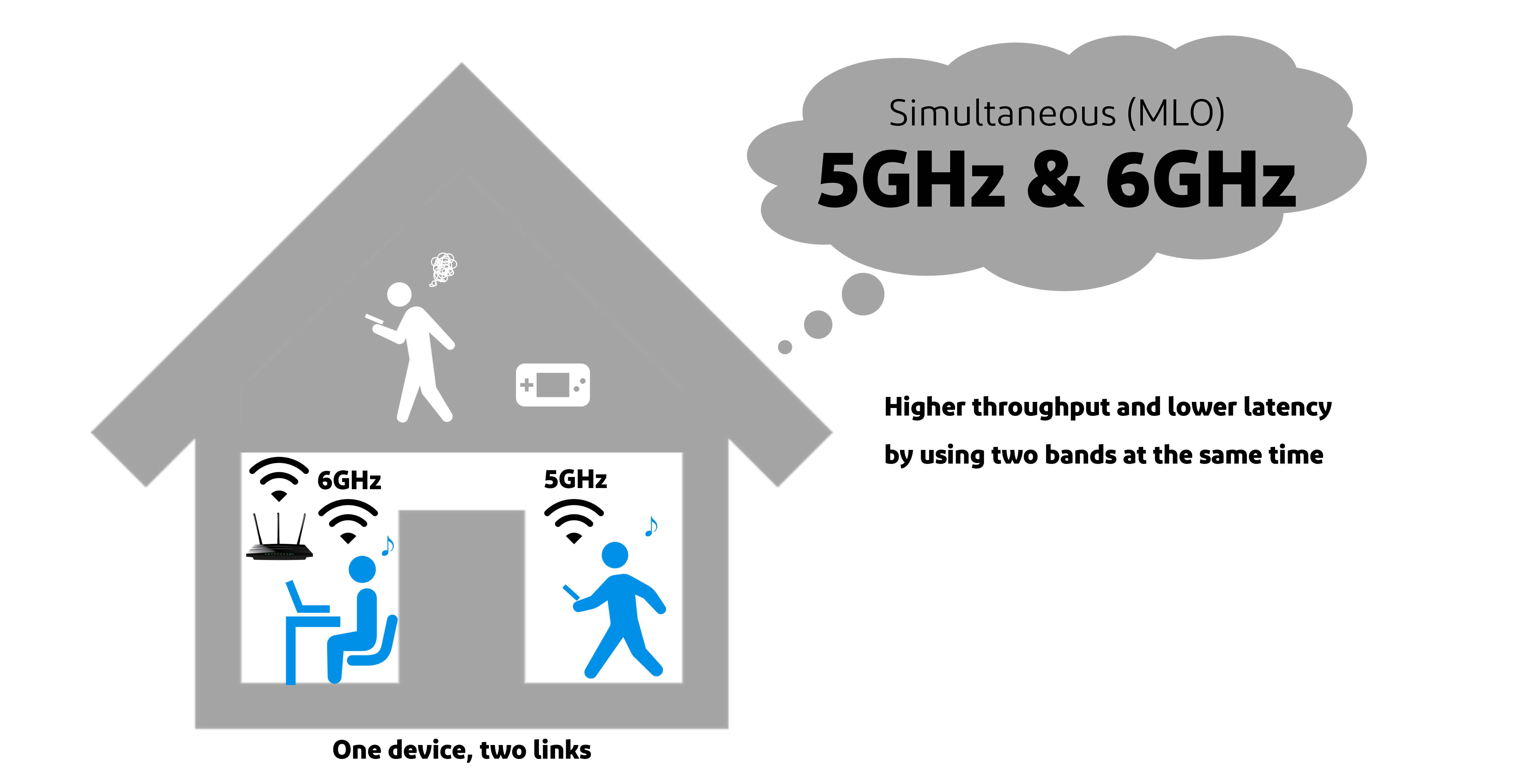
One of the most important innovations is Multi-Link Operation (MLO), which allows devices to simultaneously transmit and receive data across multiple frequency bands. This improves throughput, reduces latency, and enhances connection reliability by dynamically balancing traffic.
In addition, Wi-Fi 7 supports channel bandwidths of up to 320 MHz, doubling the maximum bandwidth available in Wi-Fi 6. This enables significantly higher data rates, especially in the relatively uncongested 6 GHz band.
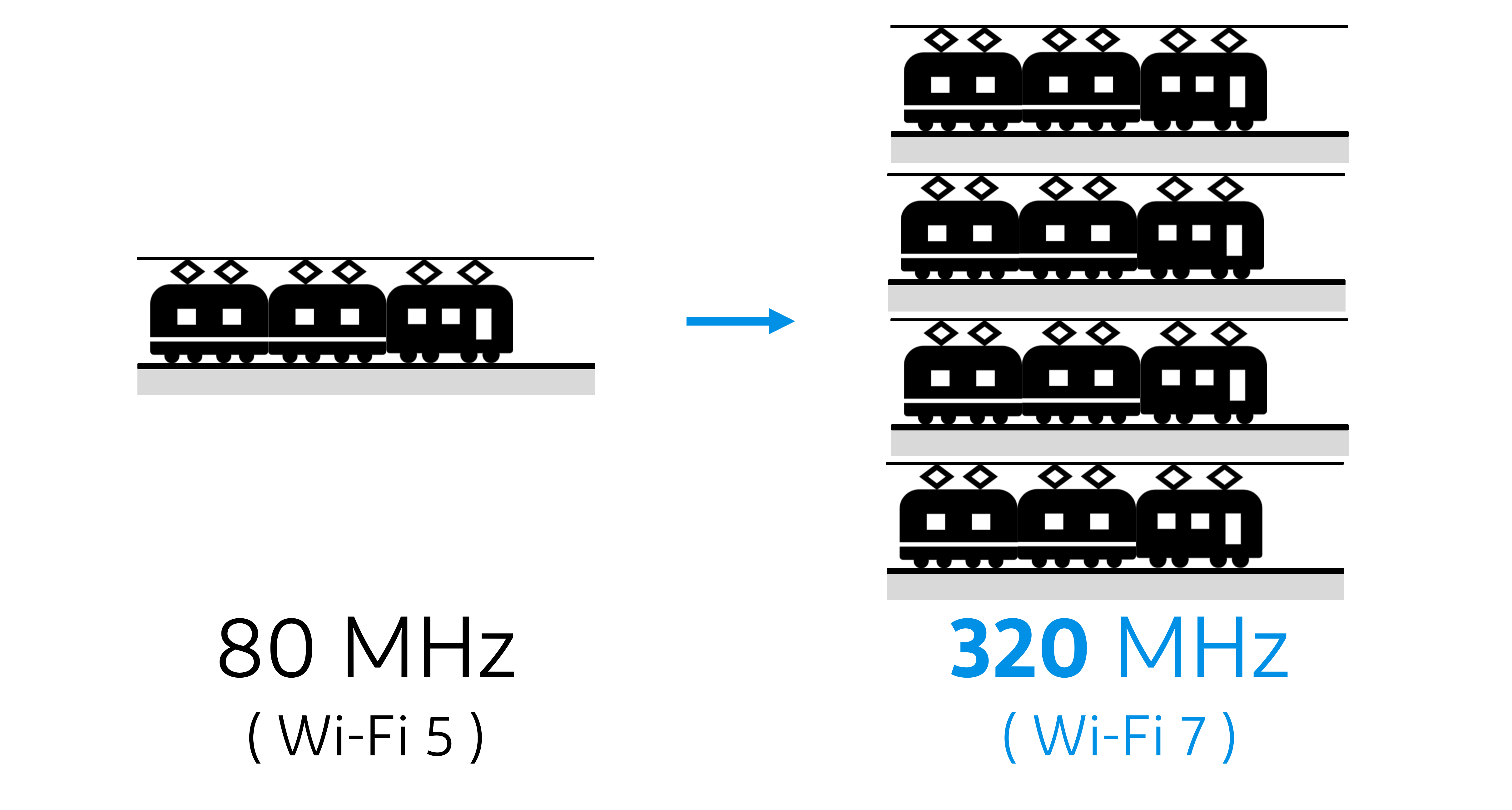
Another major improvement is more consistent and predictable low latency, which is critical for real-time applications.
These advancements make Wi-Fi 7 particularly attractive for
• High-resolution video streaming, including 8K content
• Cloud gaming and immersive entertainment
• Augmented and virtual reality (AR/VR)
• Enterprise environments with high device density
• Industrial automation and robotics
• Edge computing and real-time data processing
Understanding QAM Modulation and Its Evolution
Quadrature Amplitude Modulation (QAM) is a key technique used in Wi-Fi systems to transmit data by encoding information into variations of signal amplitude and phase. Each unique combination represents a symbol, and each symbol carries multiple bits of data.
As Wi-Fi technology evolves, higher-order QAM schemes are introduced to increase data throughput. These are presented in the table below.
| Wi-Fi Generation | Standard | QAM Level | Bits per Symbol |
| Wi-Fi 4 | 802.11n | 64-QAM | 6 bits |
| Wi-Fi 5 | 802.11ac | 256-QAM | 8 bits |
| Wi-Fi 6 | 802.11ax | 1024-QAM | 10 bits |
| Wi-Fi 7 | 802.11be | 4096-QAM | 12 bits |
By increasing from 1024-QAM to 4096-QAM, Wi-Fi 7 improves spectral efficiency by approximately 20%. However, this gain comes with stricter requirements for signal quality. As constellation points become more densely packed, the system becomes increasingly sensitive to noise, distortion, and interference.
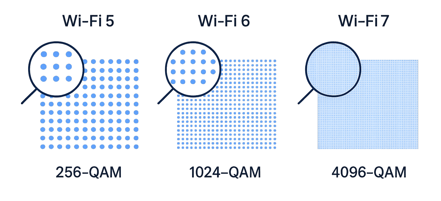
In practical terms, higher-order QAM enables faster data rates, but only when the signal environment is sufficiently clean and stable.
Challenges of Higher Frequencies and 4K-QAM
While Wi-Fi 7 delivers substantial performance improvements, it also introduces significant technical challenges, particularly due to the use of higher frequencies and more complex modulation schemes.
Higher-order modulation such as 4096-QAM requires a very high signal-to-noise ratio (SNR). Even small amounts of noise or distortion can lead to symbol errors and reduced performance.
Key challenges include:
• Increased susceptibility to noise and interference
• Signal attenuation at higher frequencies, especially in the 6 GHz band
• Reflections caused by impedance mismatches
• Crosstalk between adjacent signal paths
• Phase noise affecting signal integrity
Maintaining proper impedance (typically 50 ohms in RF systems) across the entire signal path is critical to minimizing reflections and ensuring efficient power transfer.
Impact of Connector and Cable Harnesses
As operating frequencies increase, physical design becomes more critical. Shorter wavelengths mean that even small discontinuities in the signal path can significantly degrade performance.
Important factors include:
• Quality of coaxial cables and shielding
• Connector design and impedance consistency
• Mechanical tolerances and assembly accuracy
• PCB layout precision and material selection
In Wi-Fi 7 systems, the margin for error is much smaller than in previous generations. Poor implementation in any part of the RF chain can prevent the system from achieving the benefits of 4096-QAM and wide channel bandwidths.
The Role of High-Performance Connectors in Wi-Fi 7
At Wi-Fi 7 performance levels, maintaining signal integrity across the RF path becomes essential. Connectors, in particular, play a critical role in ensuring consistent impedance, minimizing loss, and preserving signal quality.
I-PEX connectors are designed to meet the demanding requirements of next-generation wireless systems.
Key advantages include:
• Optimized performance for high-frequency operation, including the 6 GHz band and beyond
• Low insertion loss and stable electrical characteristics
• Precise impedance control to reduce reflections and signal distortion
• EMI shielding to prevent external electromagnetic noise from entering the RF path
• Compact form factors suitable for high-density device integration
• Reliable mechanical performance under thermal and physical stress
• Locking mechanisms to reduce risk of signal degradation due to vibration and shock
By ensuring a clean and stable transmission path, high-quality connectors enable devices to fully utilize advanced features such as 4096-QAM and Multi-Link Operation.
Comparison Summary
A side-by-side comparison of the two standards is shown in the table below.
| Feature | Wi-Fi 6 | Wi-Fi 7 |
| IEEE standard | 802.11ax | 802.11be |
| Max theoretical speed | Up to 9.6 Gbps | Up to 46 Gbps |
| Channel width | Up to 160 MHz | Up to 320 MHz |
| Frequency bands | 2.4 GHz, 5 GHz, 6 GHz with Wi-Fi 6E |
2.4 GHz, 5 GHz, 6 GHz |
| Modulation | 1024-QAM | 4096-QAM |
| Multi-link operation | No | Yes |
| Latency | Low | Lower, especially under congestion |
| Efficiency in busy networks | Strong | Better, especially with MLO and wider channels |
| Best use cases | Everyday streaming, gaming, video calls | High-density homes, fast transfers, AR/VR, low-latency gaming |
Conclusion
Wi-Fi 7 represents a major advancement in wireless technology, delivering significantly higher speeds, lower latency, and improved multi-device performance compared to Wi-Fi 6. These gains are made possible through innovations such as 4096-QAM, 320 MHz channels, and Multi-Link Operation.
However, achieving this level of performance requires careful attention to system design, particularly in managing signal integrity at higher frequencies. As a result, the quality of components such as connectors and cable harnesses becomes increasingly important.
For device manufacturers and system designers, success with Wi-Fi 7 depends not only on adopting the new standard, but also on ensuring that every element of the RF chain is optimized to support its demanding technical requirements. In this context, I-PEX high-performance interconnect solutions — including precision electromechanical RF connectors, effective EMI shielding, and robust mechanical locking — play a vital role.
Introduction of MHF® series
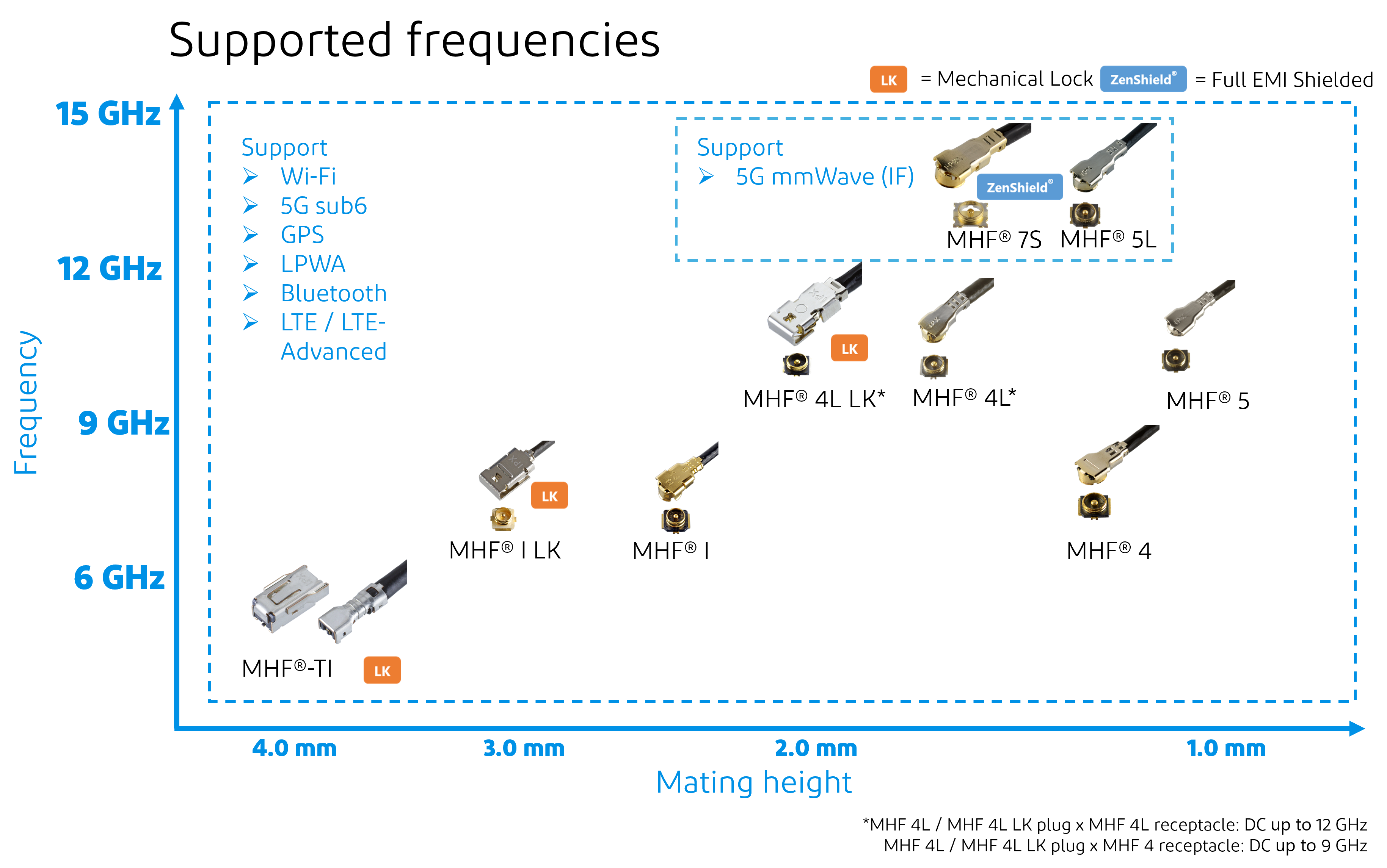
I-PEX offers an extensive line of MHF® micro RF connector series for Wi-Fi 6 / Wi-Fi 6E / Wi-Fi 7 applications.
MHF® I LK
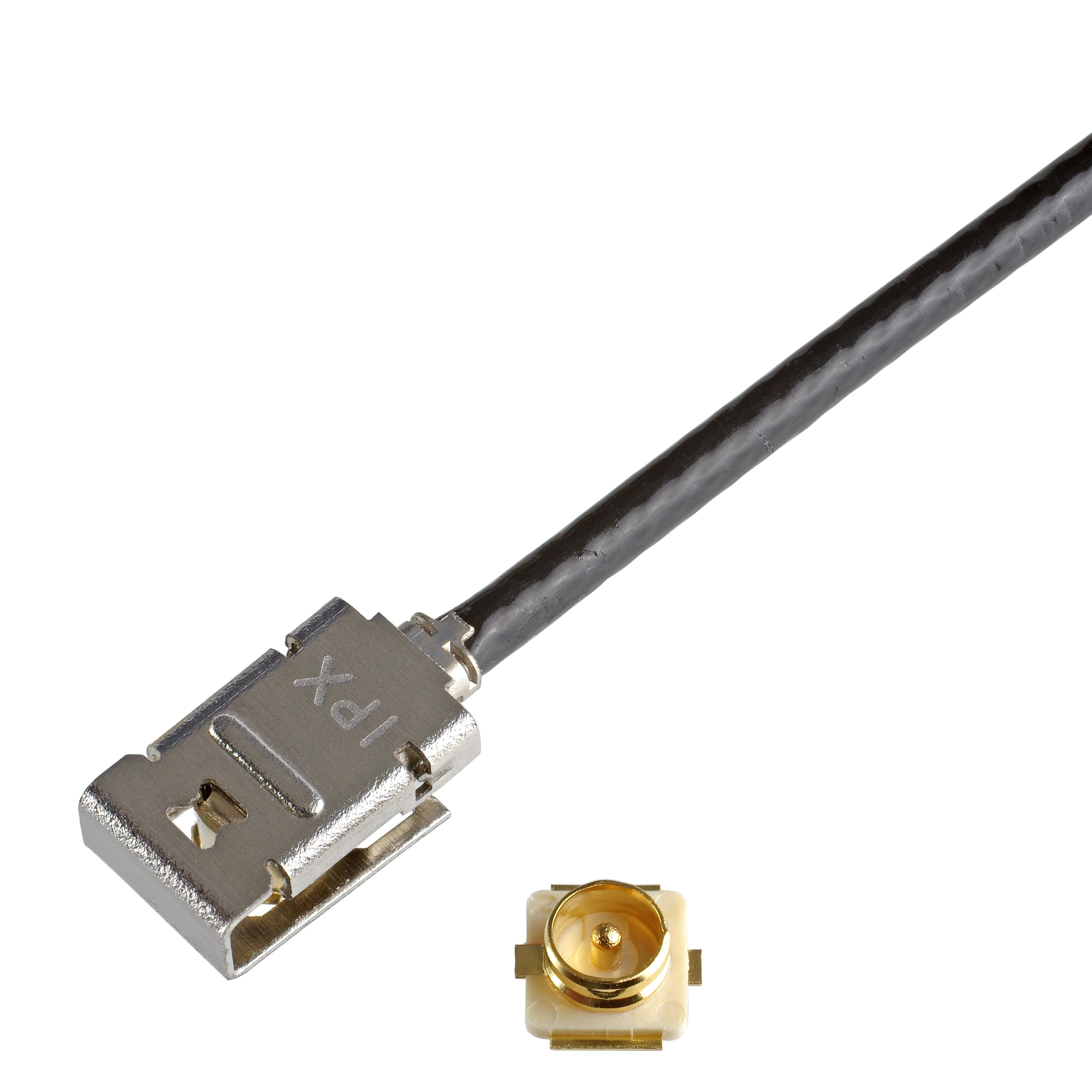
Secure mechanical locking solution that works with MHF® I receptacles, up to 9 GHz, 2.9 mm max. mated height RF connector
• Mated Height: 2.9 mm max.
• Frequency Range: Up to 9 GHz
• Cable Size (Micro-Coaxial): AWG 30 O.D. 1.8 mm, AWG 30 O.D. 1.37 mm, AWG 32 O.D. 1.32 mm, AWG 32 O.D. 1.13 mm, AWG 36 O.D. 0.81 mm
Click to watch MHF® I LK product video
MHF® I
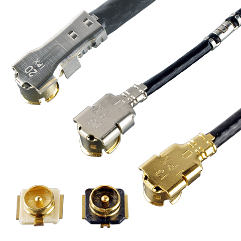
Reliable industry standard for RF antenna connections, up to 9 GHz, 2.5/3.0 mm max. mated height RF connector
• Mated Height: 2.5 mm max., 3.0 mm max.
• Frequency Range: Up to 9 GHz
• Cable Size (Micro-Coaxial): AWG 26 O.D. 2.0 mm, AWG 30 O.D. 1.8 mm, AWG 30 O.D. 1.37 mm, AWG 32 O.D. 1.32 mm, AWG 32 O.D. 1.13 mm, AWG 36 O.D. 0.81 mm
MHF® 4L LK
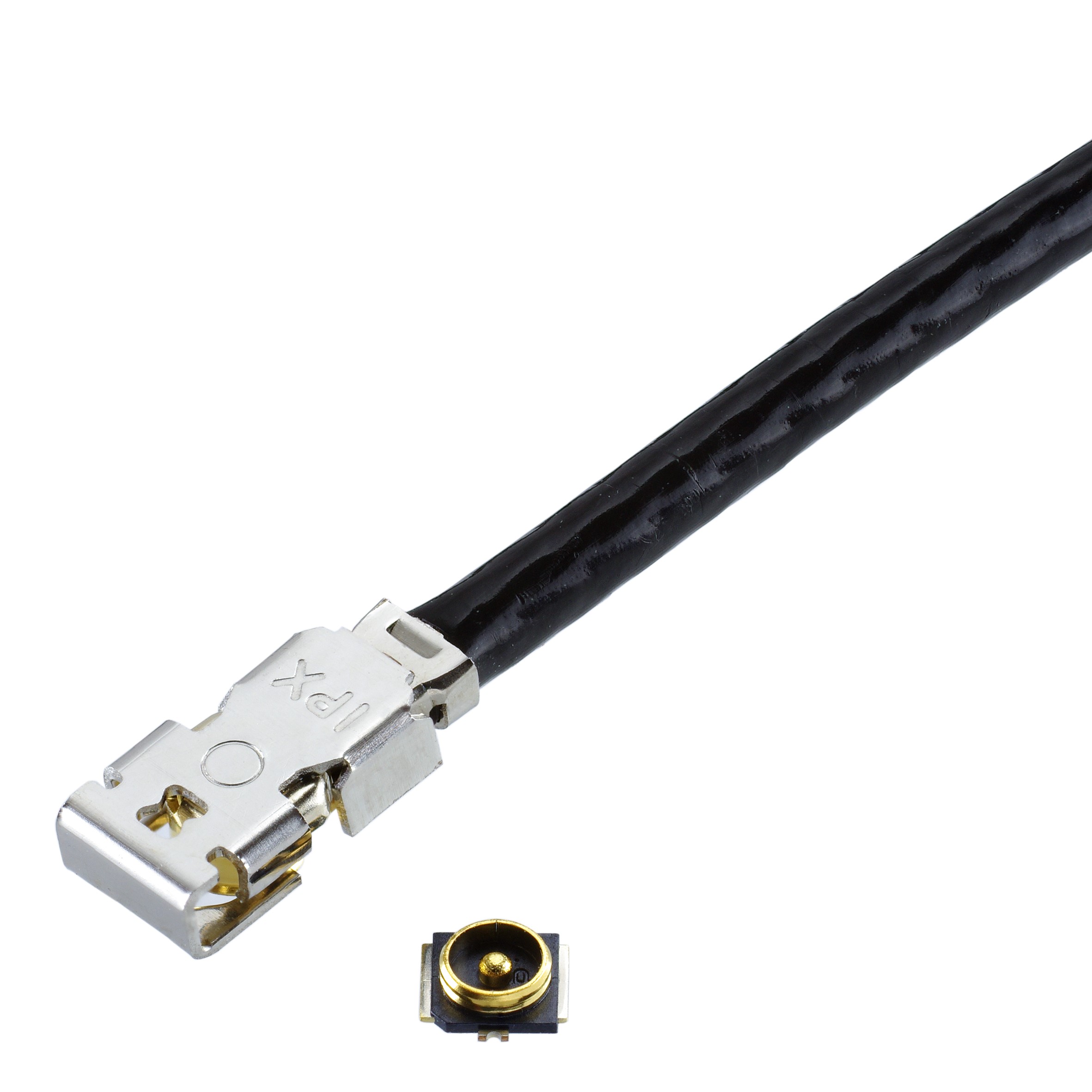
High-frequency mechanical locking solution for MHF® 4/4L receptacles, up to 12 GHz, 2.0 mm max. mated height RF connector
• Mated Height: 2.0 mm max.
• Frequency Range: Up to 12 GHz (MHF®4L receptacle), Up to 9 GHz (MHF®4 receptacle)
• Cable Size (Micro-Coaxial): AWG 30 O.D. 1.37 mm
MHF® 4L
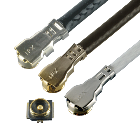
The M.2 industry standard with excellent electrical performance, up to 12 GHz, 1.2 mm, 1.4 mm, and 1.7 mm max. mated height RF connector
• Mated Height: 1.7 mm max., 1.4 mm Max., 1.2 mm max.
• Frequency Range: Up to 12 GHz (MHF®4L receptacle), Up to 9 GHz (MHF®4 receptacle)
• Cable Size (Micro-Coaxial): AWG 30 O.D. 1.37 mm, AWG 32 O.D. 1.13 mm, AWG 33 O.D. 0.95 mm, AWG 36 O.D. 0.64 mm, AWG 36 O.D. 0.81 mm
MHF® 5L
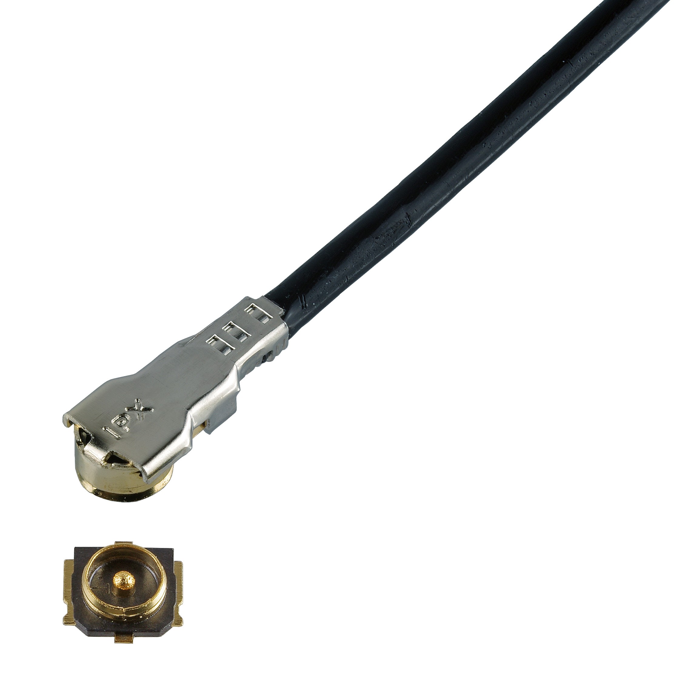
High-performance design with excellent VSWR for advanced frequency bands, up to 15 GHz, 1.3 mm max. mated height RF connector
• Mated Height: 1.3 mm max.
• Frequency Range: Up to 15 GHz
• Cable Size (Micro-Coaxial): AWG 32 O.D. 1.13 mm, AWG 33 O.D. 0.81 mm
MHF® 5
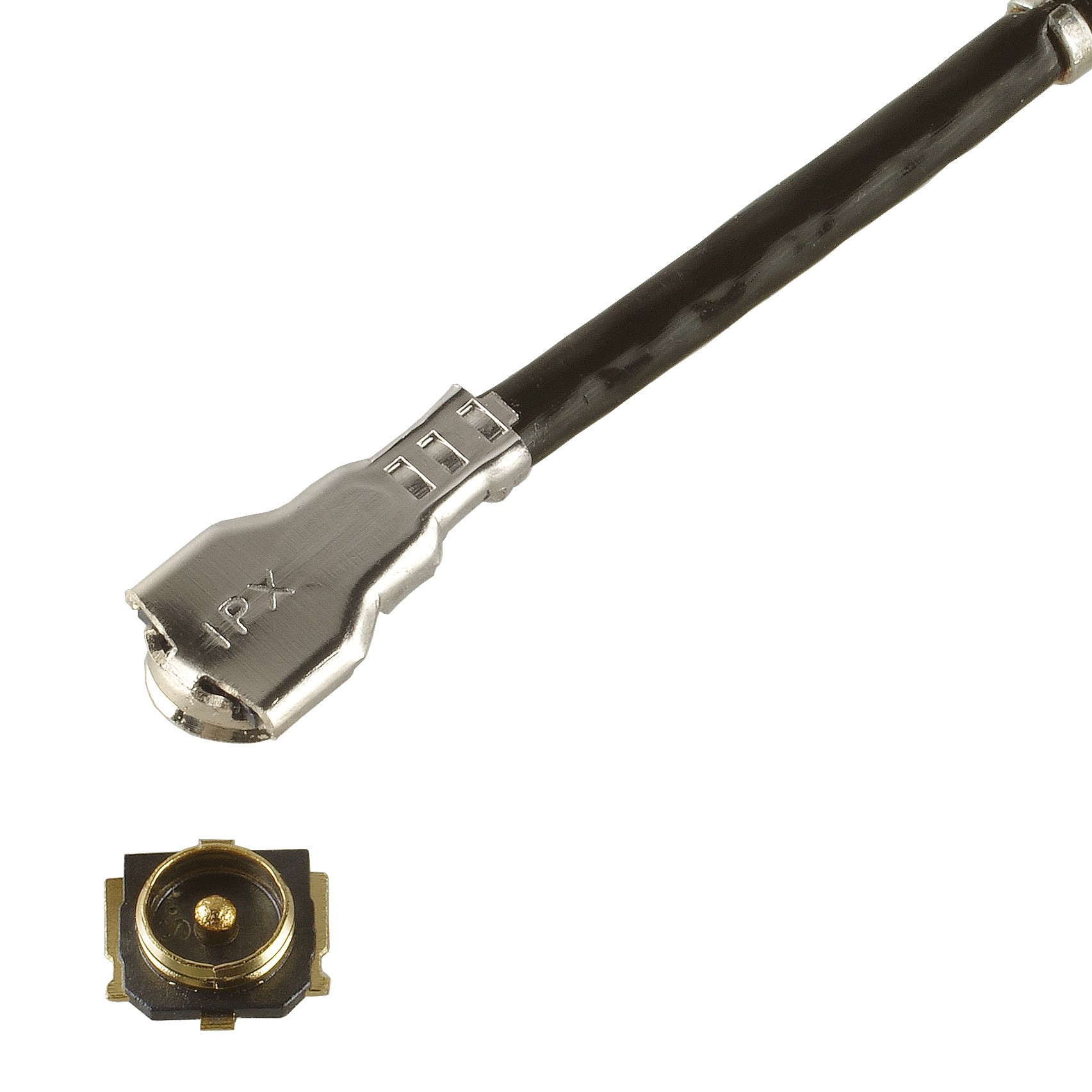
Ultra low-profile design for high-density wireless devices, up to 12 GHz, 1.0 mm max. mated height RF connector
• Mated Height: 1.0 mm max.
• Frequency Range: Up to 12 GHz
• Cable Size (Micro-Coaxial): AWG 36 O.D. 0.64 mm, AWG 36 O.D. 0.81 mm, AWG 38 O.D. 0.48 mm
MHF® 7S
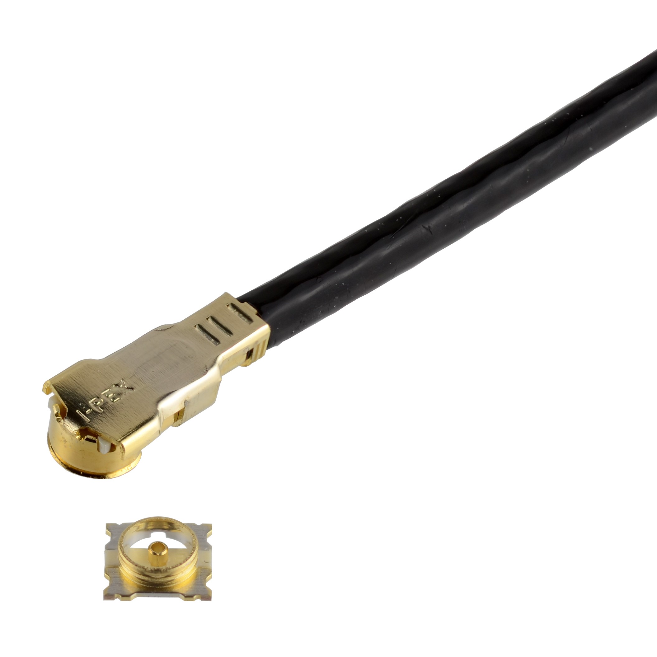
Excellent EMC performance with fully-shielded ZenShield® design for 5G mmWave, up to 15 GHz, 1.4 mm max. mated height RF connector
• Mated Height: 1.3 mm max.
• Frequency Range: Up to 15 GHz
• Cable Size (Micro-Coaxial): AWG 32 O.D. 1.13 mm


