

Superior EMC Performance
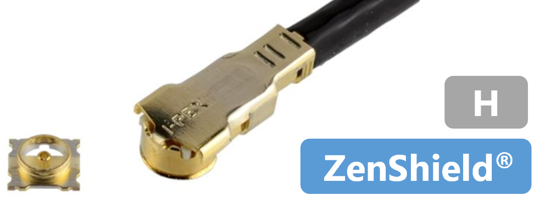
Shielding in MHF® RF connectors and harnesses is vital to preserve signal integrity, maintain impedance control, reduce interference, and maximize RF efficiency. It is not just a mechanical enclosure — it’s an integral part of the electrical design that sustains high data rates and reliable antenna performance. Idea is to minimize external EMI/ RFI, prevent cross talk and maintain the impedance consistency, thereby reducing the noise and maintaining a higher Signal-to-Noise Ratio (SNR). Unique Shielded design of MHF® 7S series connectors reduces the EMI noise and offers excellent EMC performance in 5G mm wave applications. Full 360 degrees ZenShielding in MHF® 7S connectors reduces the radiated electric field emissions and allows for the closer placement of connectors to antenna elements. Figure 1 shows the reduced noise emissions with shielded MHF® 7S connectors as compared to unshielded MHF® 4L connectors.

Wireless environments are full of noise sources — switching regulators, processors, displays, and other radios. Unshielded antenna connectors or cables can pick up this noise, causing signal distortion, frequency drift, or loss of modulation accuracy. In multi-antenna (MIMO) or multi-signal environments, unshielded lines can leak energy into adjacent signal paths, degrading isolation between channels. RF paths are impedance-controlled (typically 50 Ω). Without proper shielding, nearby conductors and stray fields change the impedance environment, leading to reflections, standing waves, and degraded VSWR (Voltage Standing Wave Ratio). MHF® 7S receptacles and plug harness assemblies offer excellent VSWR performance across the frequency range of DC to 15 GHz as shown in the Figure 2 below.
Graph in the Figure 2 below shows the strength of radiated electric field around MHF® 4L and MHF® 7S Harness Assemblies. It can be seen that there is less radiated electric field for MHF® 7S Harness since the integrated 360 degrees Zenshield® provides better shielding, keeping most of the electric field inside the Harness at all frequencies.

Please visit below product page for technical information about MHF® 7S and sample requests.
Product Name |
MHF® 7S |
|
Appearance |
|
|
Feature |
Excellent EMC performance with fully-shielded design |
|
Part Number |
Plug |
20980-001R-13 |
Receptacle |
20981-001E-02 |
|
Mated Height |
1.4 mm max. |
|
SMT Size |
2.0 x 2.0 mm |
|
Cable Size
|
3.0 mm |
- |
2.8 mm |
- |
|
2.0 mm |
- |
|
1.8 mm |
- |
|
1.37 mm |
- |
|
1.32 mm |
- |
|
1.13 mm |
AWG 32 |
|
0.95 mm |
- |
|
0.84 mm |
- |
|
0.81 mm |
- |
|
0.64 mm |
- |
|
0.48 mm |
- |
|
Frequency Range |
Up to 15 GHz |
|
VSWR
|
DC to 3 GHz |
1.3 max. |
0.3 to 3 GHz |
- | |
3 to 6 GHz |
1.35 max. |
|
6 to 9 GHz |
1.4 max. |
|
9 to 12 GHz |
1.45 max. |
|
12 to 15 GHz |
1.5 max. |
|
Operating Temperature |
-40 to 90℃
|
|
Automotive Standards |
- |
|
(*) Rev.6 - 5.4.6 (Vibration), 5.6.1 (Thermal Shock), 5.6.2 (Temp. & Humidity Cycle), 5.6.3 (High Temp. Exposure & Life) evaluation passed.
Features and Benefits of I-PEX RF Solutions
- 1. Compact Size and High Density
- 2. High Frequency and Data Rates
- 3. Superior EMC Performance
- 4. High Design Flexibility
- 5. Robust Design with Integrated Locking Features
- 6. Key Industry Standards
- 7. Consistent Performance with i-Fit® Technology
- 8. MHF® Switch Products for Antenna Testing
- 9. Available Accessories
- 10. PCB Stack Up Optimization Services
- 11. Signal Integrity Data
- 12. Signal Integrity Testing


