

Key Points of Micro-Coaxial Harness Design
This article provides an overview of the key design considerations for micro-coaxial harnesses used with I-PEX CABLINE® series connectors.
By following these guidelines, customers can improve signal integrity, reduce EMI issues, and ensure reliable harness assembly.
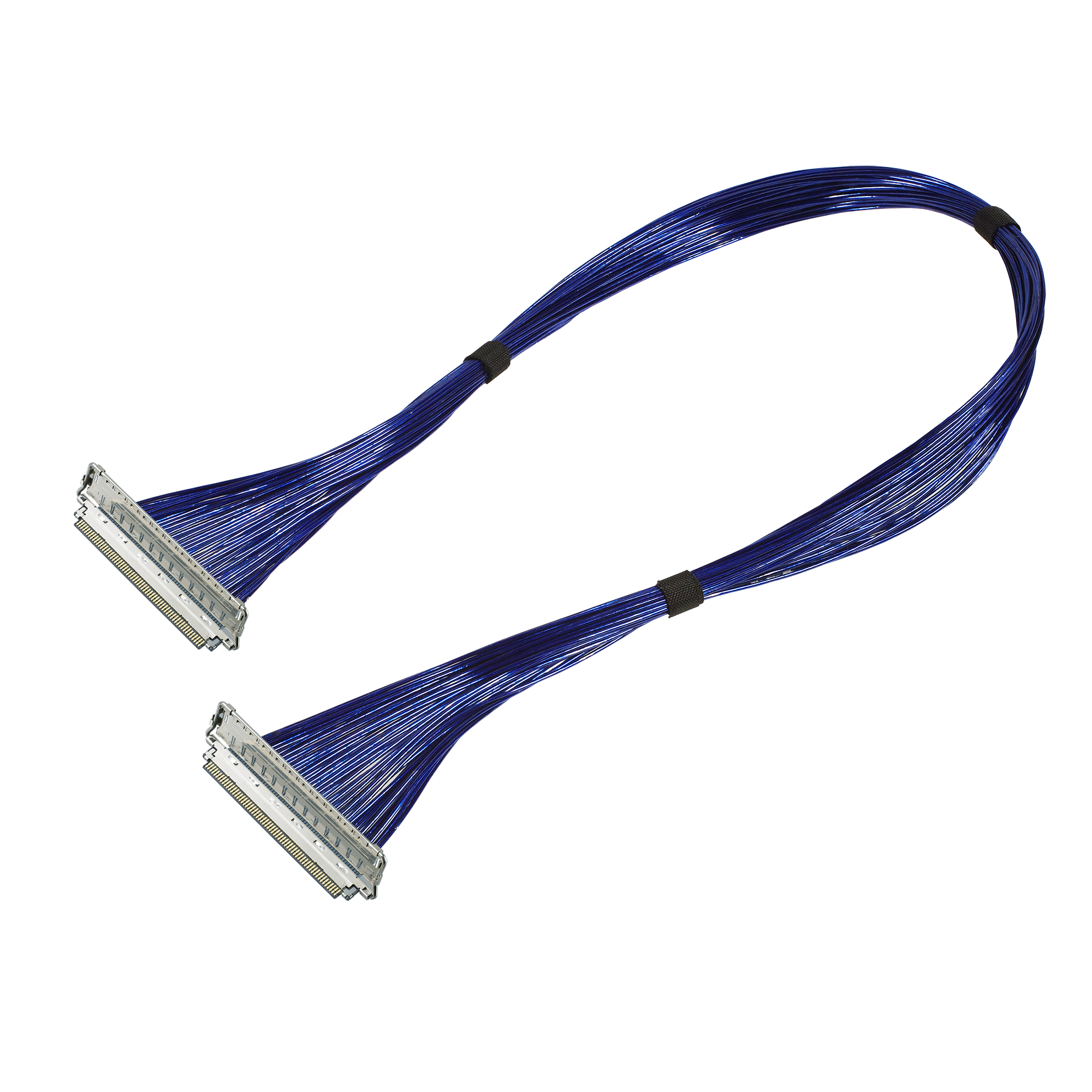
1. Applicable Cable
I-PEX CABLINE® connectors support the following cable types:
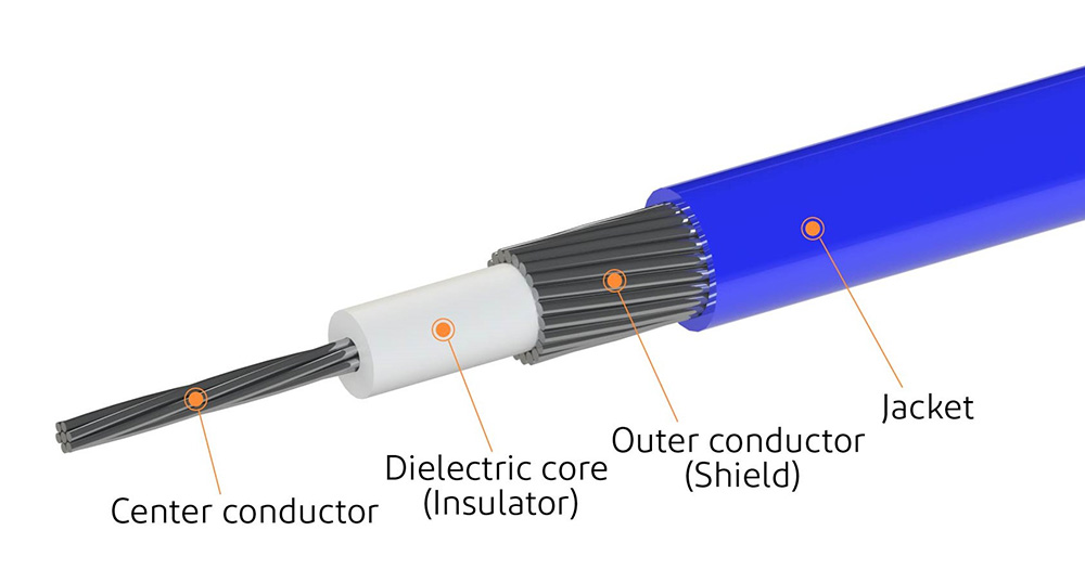
Micro-coaxial cable
Micro-coaxial cables are designed for high-frequency signal transmission and provide excellent shielding against electromagnetic interference (EMI).
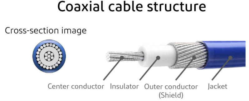
A typical structure includes:
• Center conductor (signal transmission)
• Dielectric layer (insulation)
• Outer conductor/shield (ground path)
• Outer jacket
These cables are available with controlled characteristic impedances of 42.5 ohm, 45 ohm, and 50 ohm, with 30 ohm options for power lines.
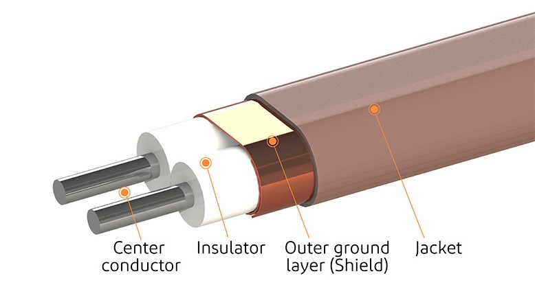
Twinaxial cable
Twinaxial cables are used for differential signal transmission and offer:
• Low skew
• Low loss
• High-speed performance
Typical differential impedances: 85 ohm, 90 ohm, 100 ohm
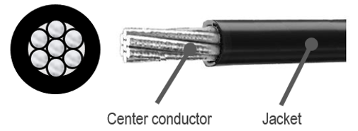
Discrete wire
Discrete wires are mainly used for power transmission and do not have controlled characteristic impedance.
Information on CABLINE® series connectors and their compatible cables can be found via the link below.
Reference material: Connector Matrix
2.Cable size (AWG)
AWG (American Wire Gauge) indicates conductor size.
• Higher AWG number → smaller diameter
Proper selection affects:
• Electrical performance
• Compatibility with connector pitch
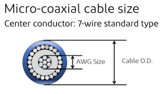
AWG size (American Wire Gauge) is a standard that represents the thickness (diameter or cross-sectional area) of electrical wires (conductors).
Please refer to the link for more detailed cable information: How to Select a Micro-Coaxial Connector
3. Description and Function of the Ground Bar/Ground Finger
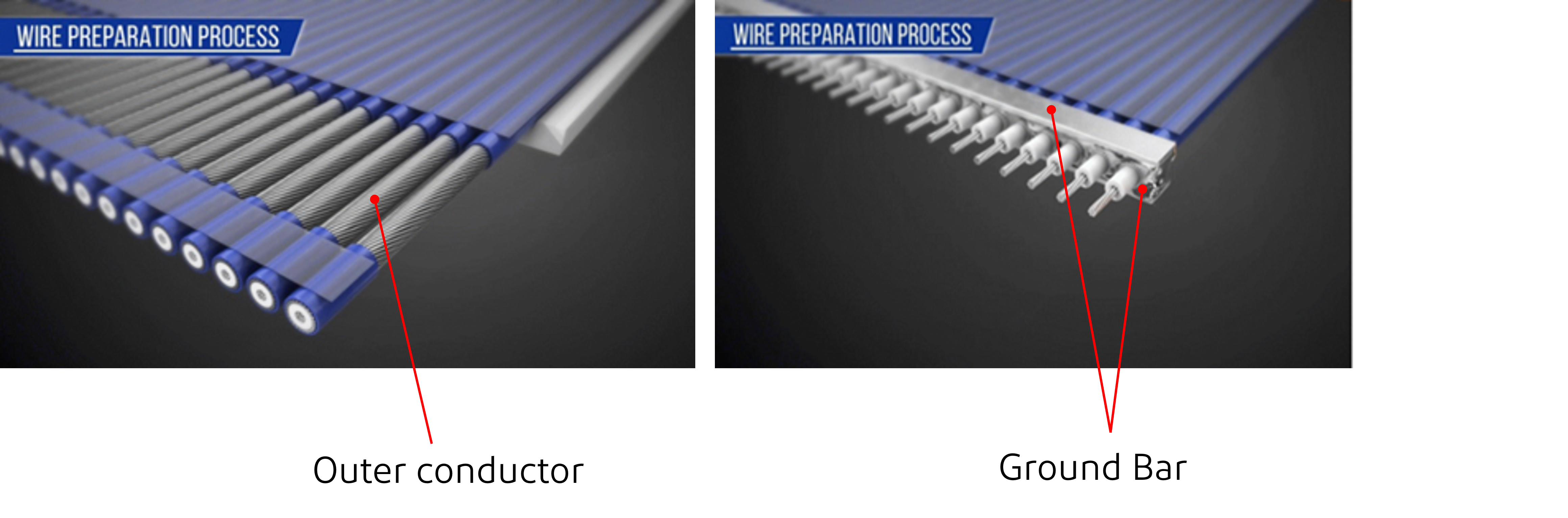
The ground bar connects the cable shield to the connector shell and provides a stable grounding path.
• Ensures proper current return path
• Improves EMI performance
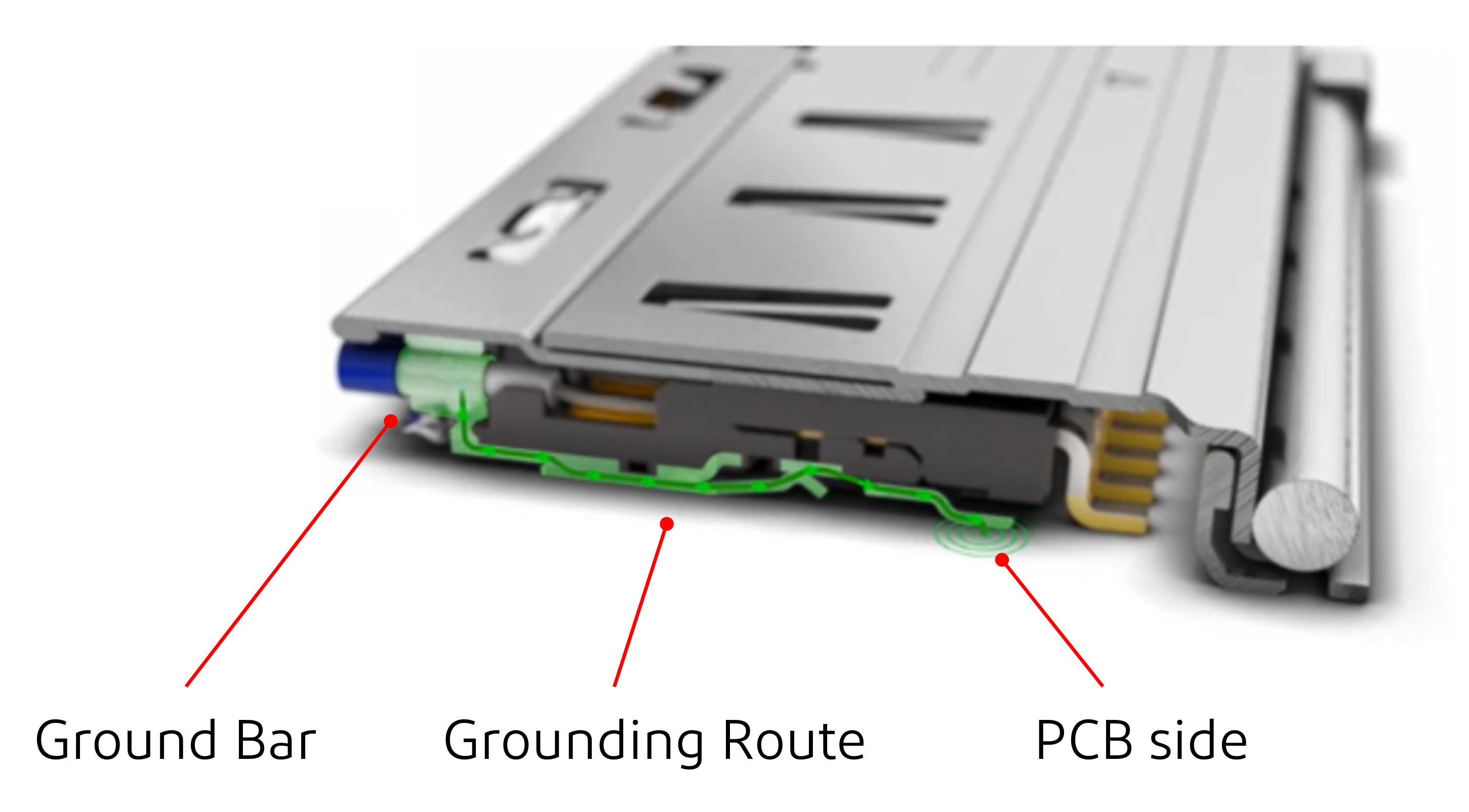
The grounding path for the connector is shown in the diagram below.
The design ensures adequate current return paths by providing proper multipoint grounding between the plug and receptacle shields during mating, as well as grounding to the PCB.
The grounding structure helps protect against external electromagnetic noise and prevents electromagnetic noise generated by signals within the connector from being radiated to the surrounding environment.

You need to use both the upper and lower ground bars.
Failure to do so may result in the following problems
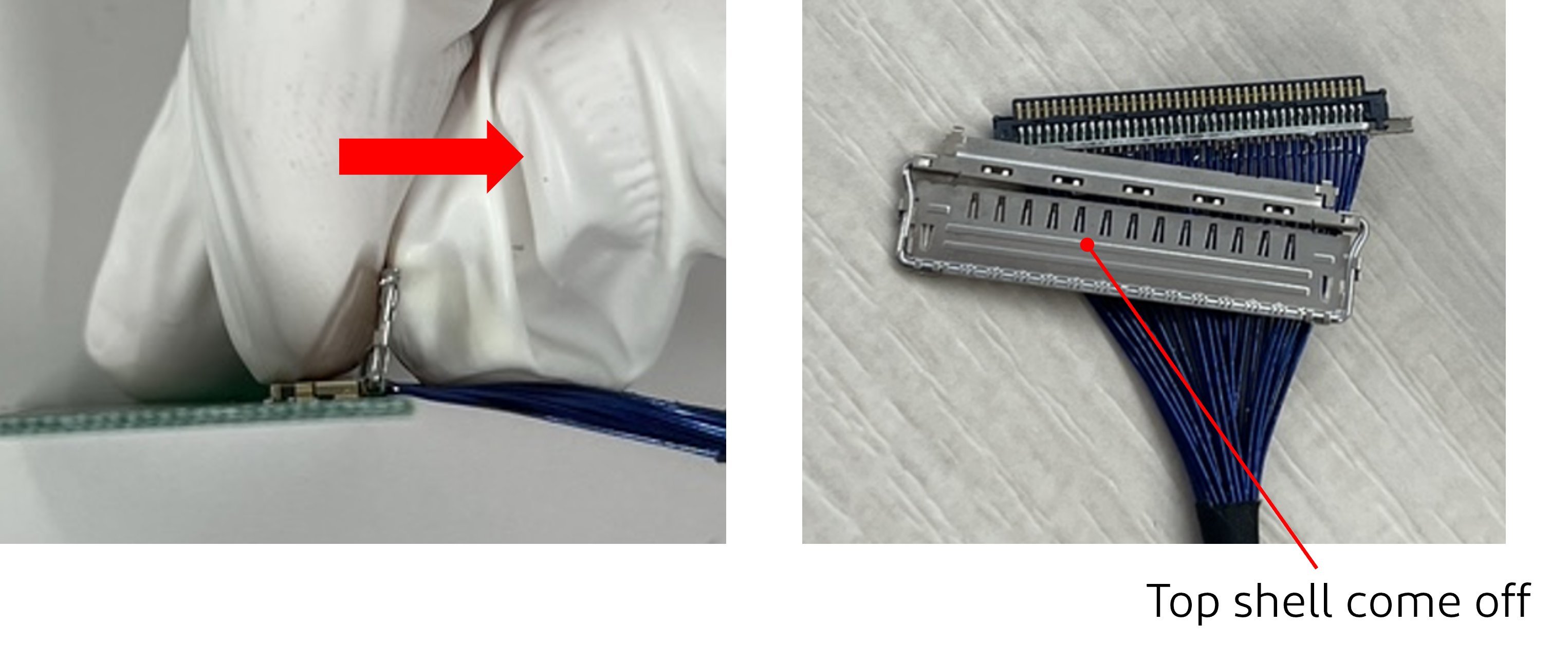
If only the lower ground bar is used
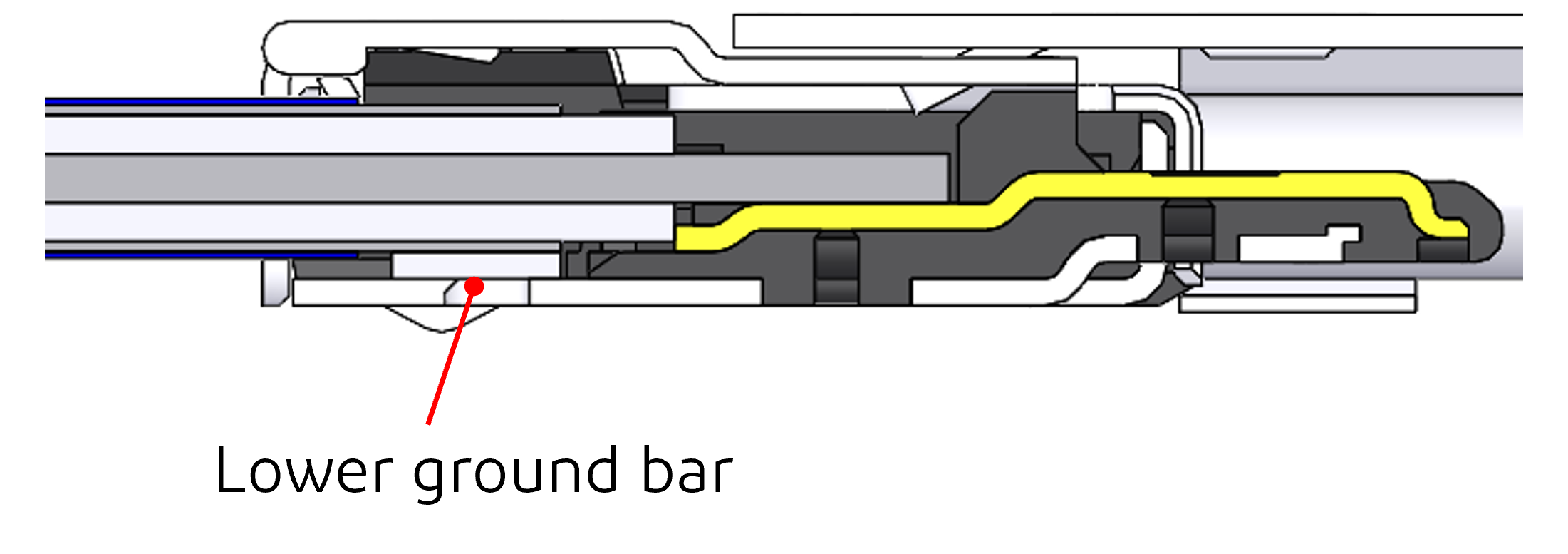
Since the shell is soldered only to the lower ground bar, the upper shell may come loose when the connector is inserted or removed.
The upper shell may detach during connector unmating.
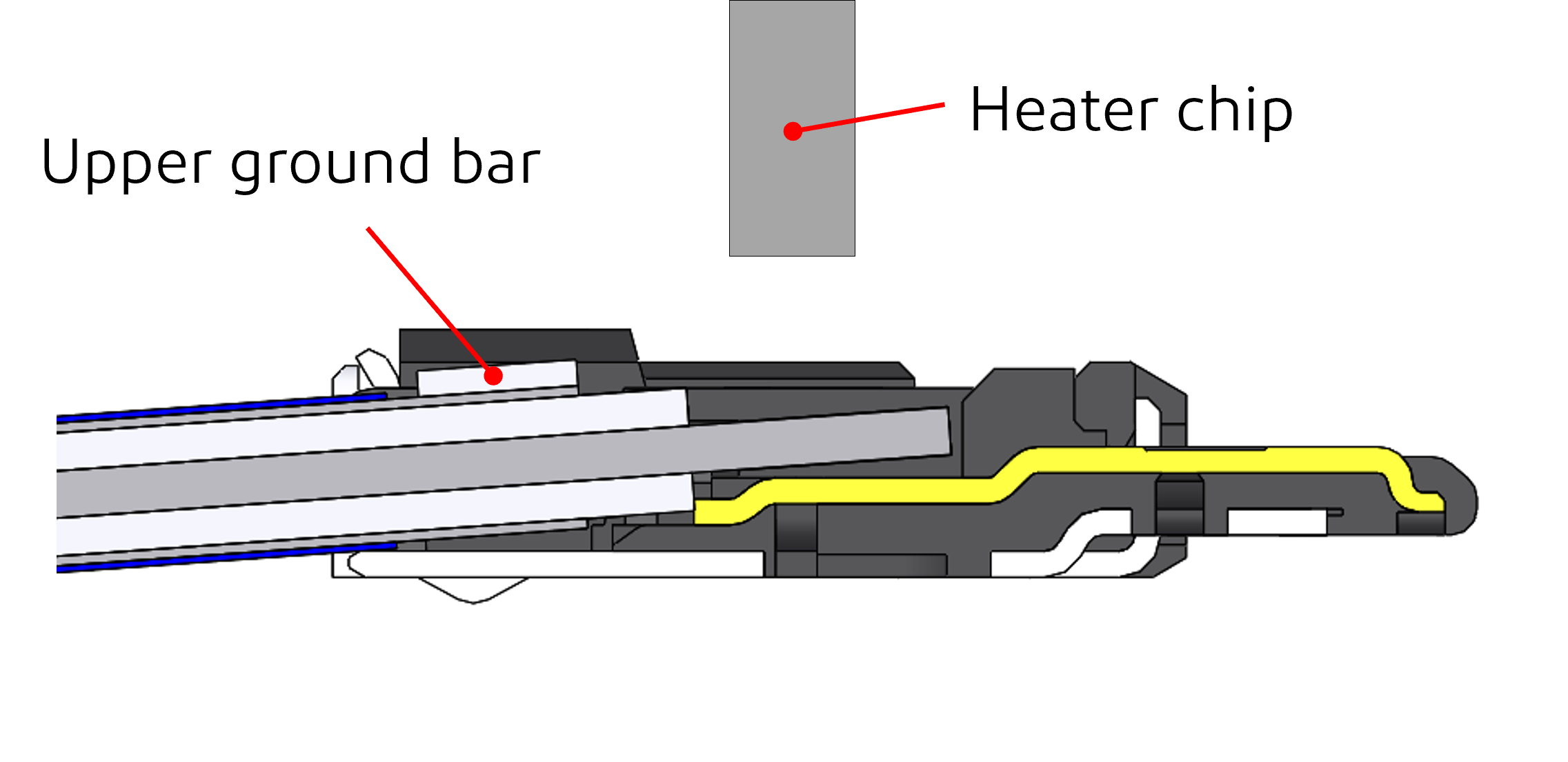
If only the upper ground bar is used
The bottom ground bar is missing.
As a result, when soldering the cable to the connector, the cable is likely to tilt, making it highly probable that the solder joint on the bridge will be defective.
Both side ground bar
This is the correct method of use.
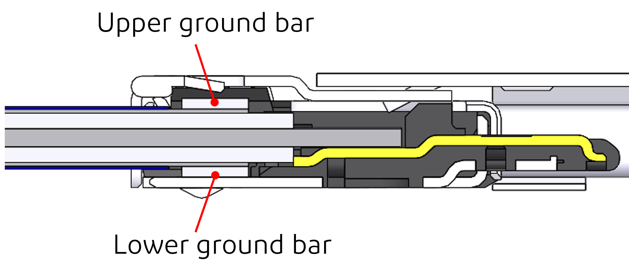
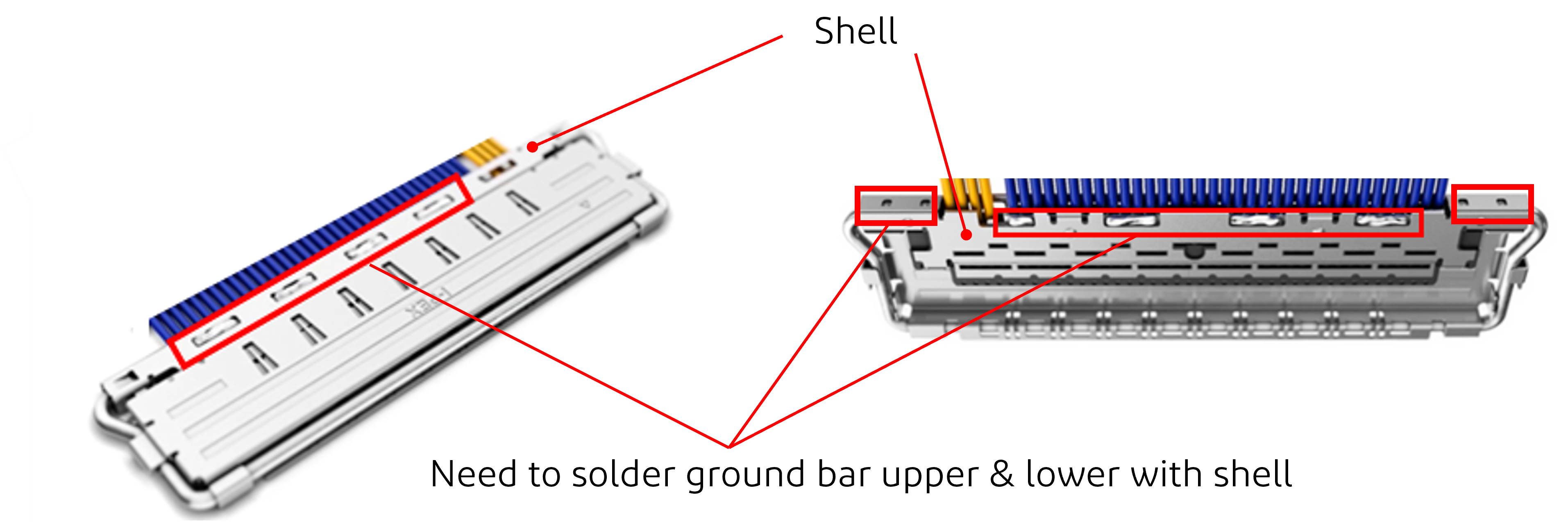
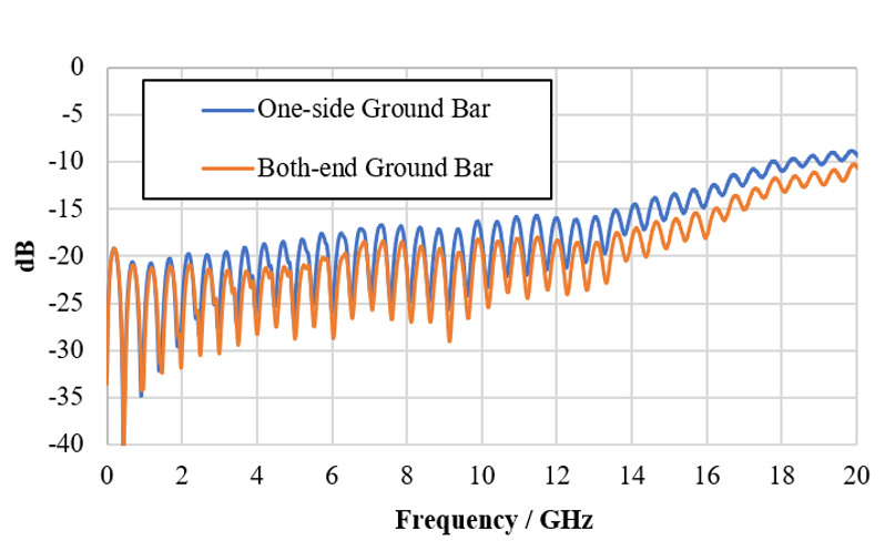
In terms of SI performance, a both-end ground bar performs better than a one-side with lower ground bar.
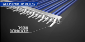
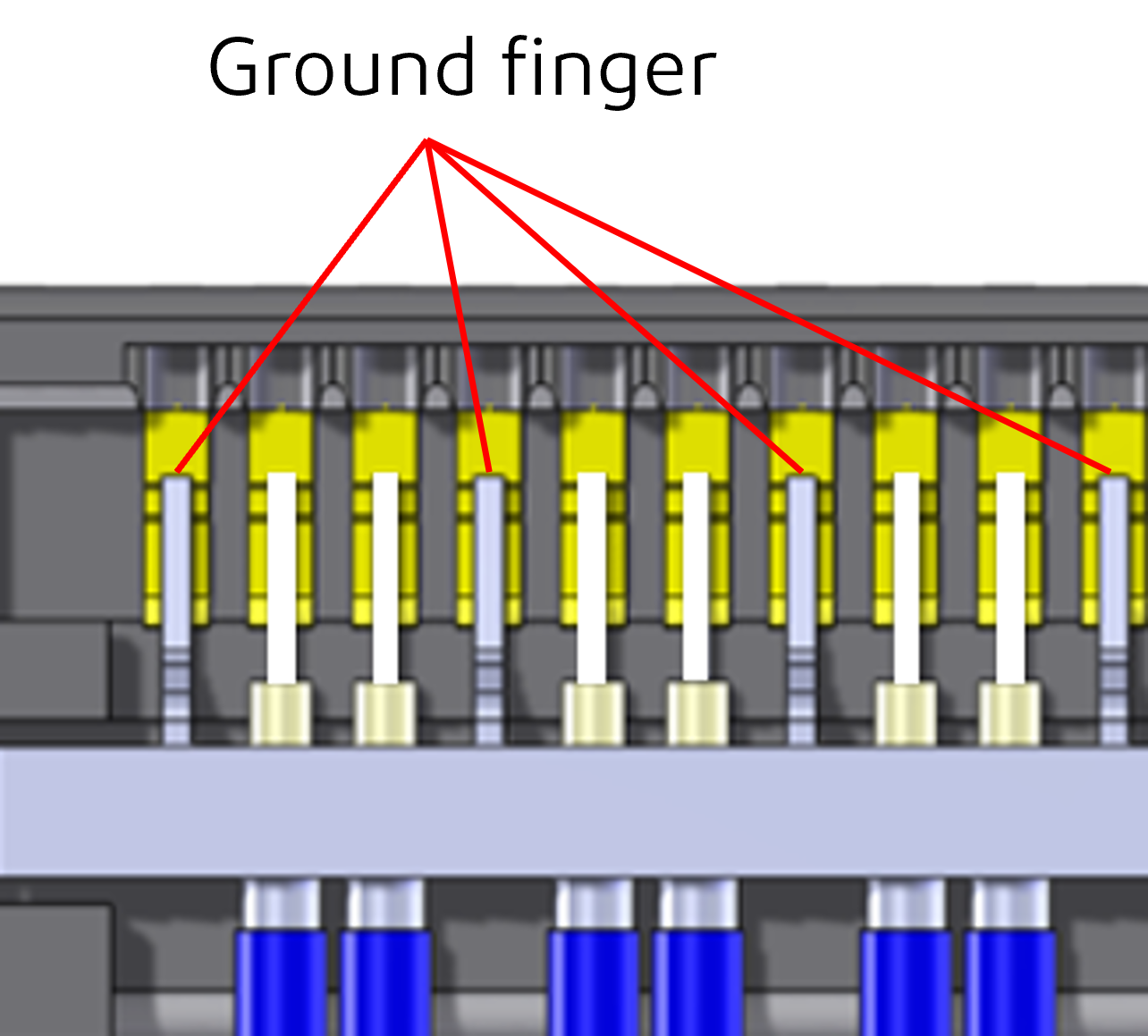
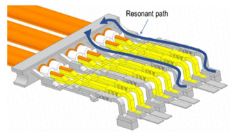
Role and effect of ground fingers
Ground fingers are inserted between signal lines.
Benefits:
• Shifts resonance to higher frequencies
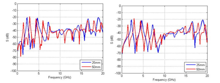
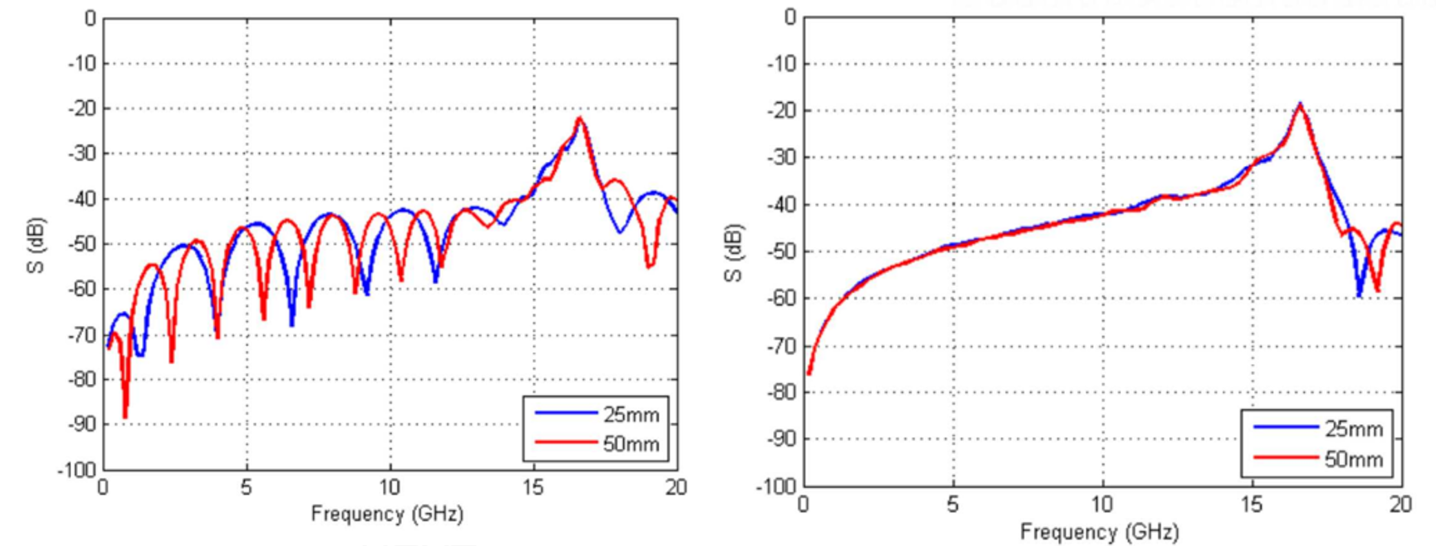
• Reduce crosstalk (NEXT/FEXT) performance
• Enables GSSG structure for better shielding
 |
 |
 |
Products with ground fingers exhibit improved crosstalk performance compared to those without ground fingers.
Without Ground finger
With Ground finger
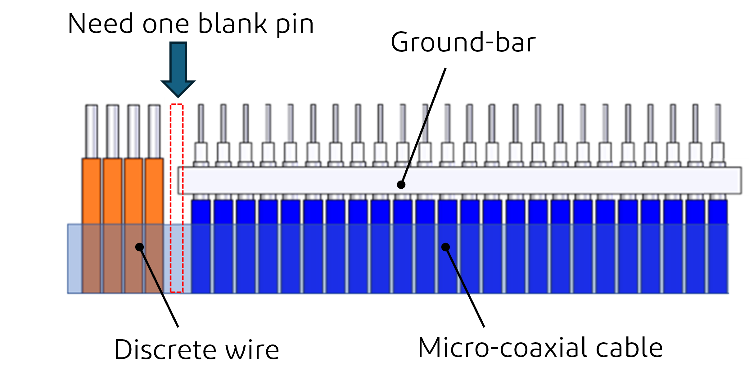
4. Important notes for Hybrid harness
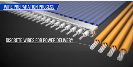
When using both micro-coaxial cables and discrete wires:
→ A one-pin blank position is required between them
Purpose:
• Prevent interference with the ground bar
• Avoid pitch misalignment
• Reduce risk of short circuits or continuity failures
 |
 |
5. Important Notes on Cable Wiring
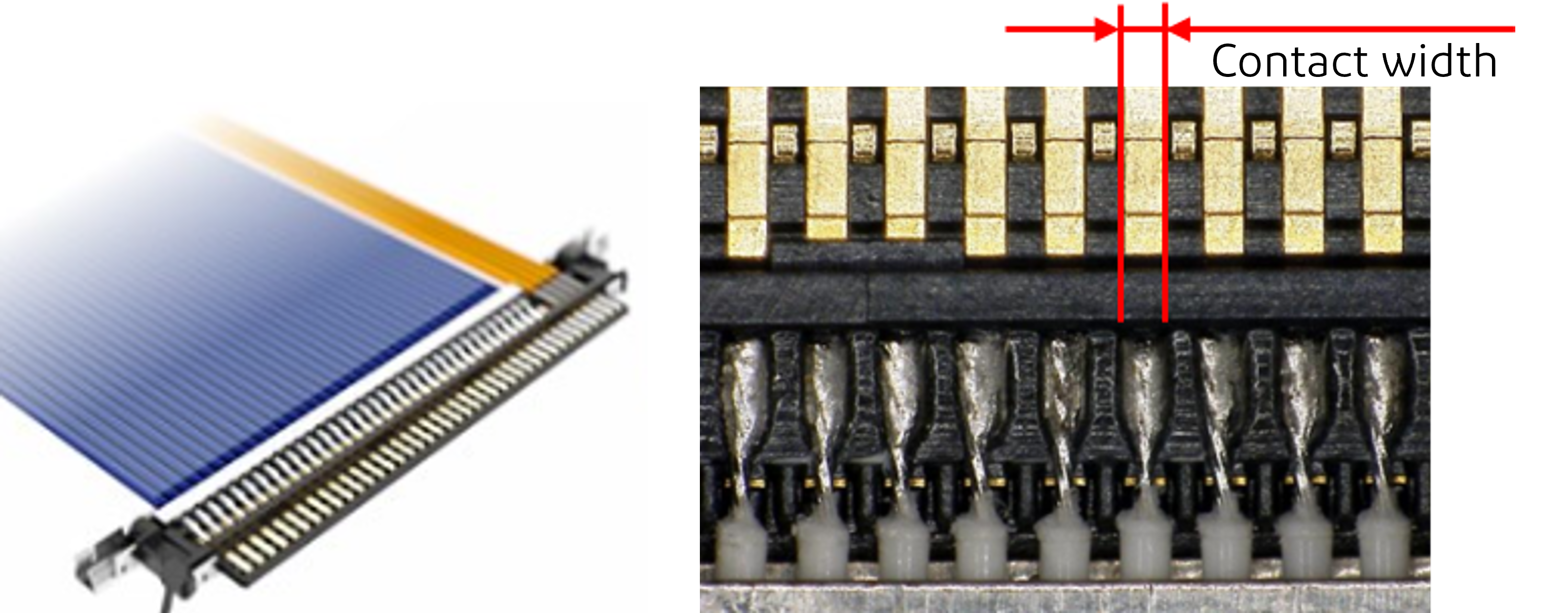
The center conductor must fit within the connector contact width.
Failure to do so increases the risk of short circuits.
Pitch refers to the distance between adjacent pins on a connector.
For fine-wire coaxial connectors, the connector pitch determines the maximum outer diameter of cable that can be used.
Using a larger, non-compliant cable significantly increases the risk of short-circuit failure.
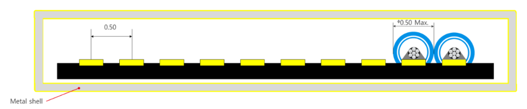
Connector pitch determines the maximum cable diameter.
| Pitch | Max Cable OD |
| 0.5 mm | 0.5 mm |
| 0.4 mm | 0.4 mm |
Using oversized cables can cause:
• Short circuits
• Assembly defects
Example 1:
10-pin connector with 0.5 mm pitch, compatible cable outer diameter 0.5 mm max.
Example 2:
10-pin connector with 0.4 mm pitch, compatible cable outer diameter 0.4 mm max.

Reference material: How to Select a Micro-Coaxial Connector
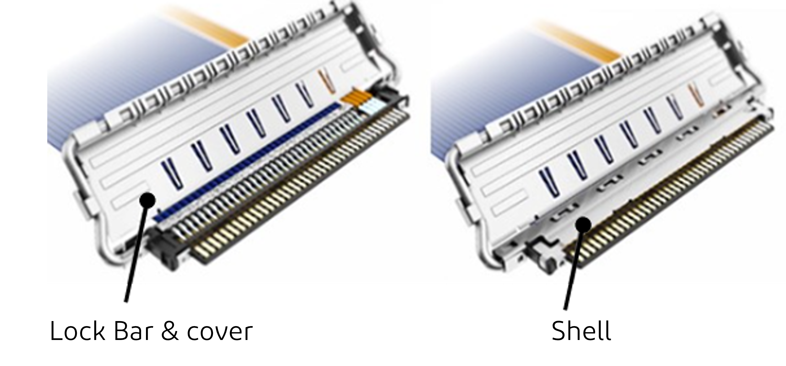
6. Important Notes for Shell & Lock Bar Assembly
• The shell improves shielding EMI performance
• The lock bar prevents accidental unmating
Correct assembly is critical for:
• Mechanical reliability
• Signal integrity
Reference material: Assembly Manual
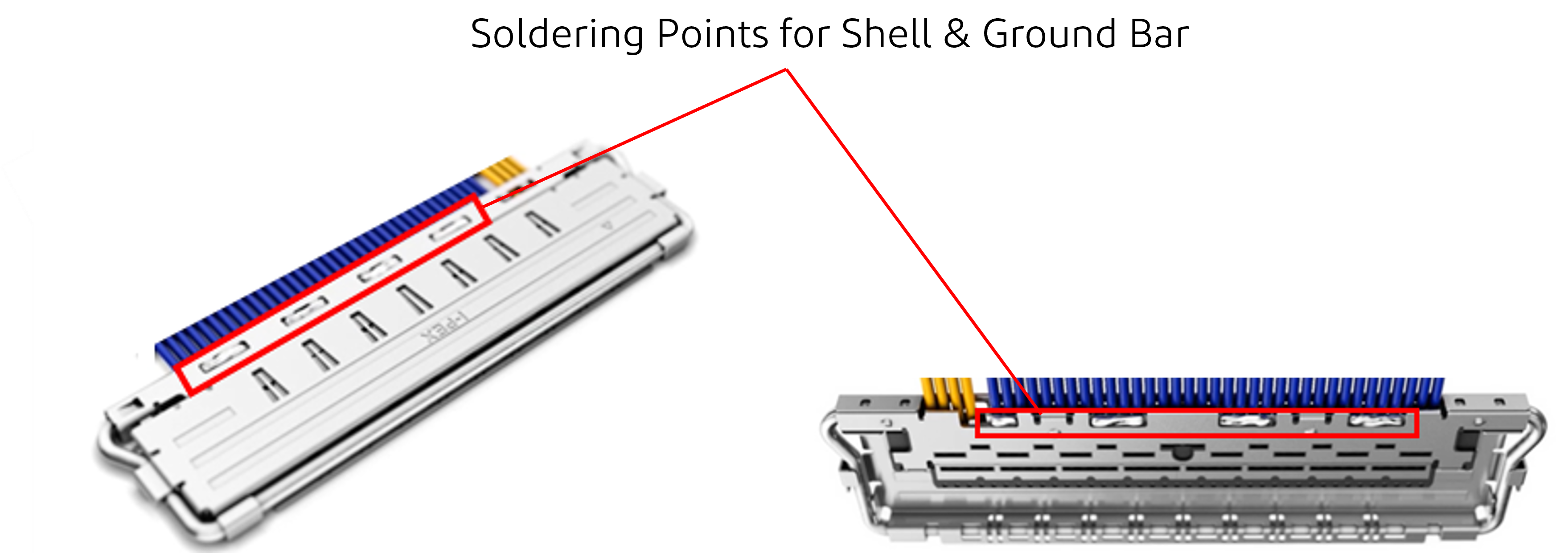
7. Precautions for Shell Soldering
Proper soldering of:
• Shell
• Ground bar
ensures:
• Stable grounding
• Improved signal integrity (SI)
8. Summary
Understanding these design points is essential to ensure:
• Reliable electrical performance
• Stable mechanical connection
• Reduced EMI and crosstalk


