

What is Signal Integrity (SI) Testing for High-Speed Transmission Connectors?
In the transmission of high-speed digital signals, connectors are one of the most important factors in determining signal quality. Particularly in high-speed interfaces such as PCIe Gen5 / Gen6, USB4, and DisplayPort, even slight variations in the characteristics of a single connector can directly affect the overall system’s Signal Integrity (SI) margin and compliance with standards.
In this article, we will outline the basics of connector Signal Integrity (SI) testing, as well as key measurement methods and evaluation metrics. Focusing on our CABLINE® series, we will also introduce key points for testing high-speed transmission connectors, whose demand is increasing in applications requiring high-speed communication, and present I-PEX's lineup of SI test boards.

1. What is Signal Integrity Testing?
Signal Integrity (SI) testing is a technique for quantitatively assessing how faithfully waveforms and timing are maintained as high-speed electrical signals pass through transmission paths (such as connectors, cables, and PCB traces). In today’s world, where high-speed interfaces such as USB, PCIe, and HDMI are widespread, the characteristics of a single connector directly impact the overall communication quality of a product.
In connector SI testing, the following factors primarily degrade signal integrity:
- ・Reflections caused by characteristic impedance mismatch
・Crosstalk between adjacent pins (NEXT / FEXT)
・Insertion loss due to conductor and dielectric losses
・Skew within differential pairs and common-mode conversion
As high-speed and high-density designs become increasingly prevalent, the ability to accurately isolate and evaluate the SI characteristics of individual connectors is critical to design quality and development efficiency.
2. Major Industry Standards
The SI characteristics of connectors are extremely important for high-speed transmission. Depending on the application, performance requirements and evaluation methods are defined by the following industry organizations and standards.
| PCI-SIG | PCI Express (Gen4 / Gen5 / Gen6) |
| USB-IF | USB4, USB Type-C |
| MIPI Alliance | D-PHY, A-PHY, C-PHY, M-PHY |
3. Measurement Equipment and Fixtures Required for SI Testing
For connector evaluation, it is common to use a VNA (Vector Network Analyzer), fixtures, and de-embedding tools from among the following.
| Equipment | Main Applications | Features |
| VNA (Vector Network Analyzer) |
Measurement of general S-parameters | The most basic SI measurement tool |
| TDR Oscilloscope | Characteristic impedance profile visualization | Effective for locating discontinuities |
| Fixtures (SI test boards, adapters, etc.) |
Measurement Interface | Customized according to the product and target frequency |
| De-embedding tool | Extracts connector characteristics | Eliminates the influence of evaluation boards and fixtures |
| BERT (Bit Error Rate Tester) |
Error rate measurement using real signals | Enables evaluation under conditions close to real-world usage |
| Real-time oscilloscope | Eye diagrams, Jitter Analysis | Detailed analysis of waveforms in the time domain |
Especially in high-speed transmission applications, the design quality of the SI test board itself can significantly affect measurement results.
4. Main Measurement Parameters
| Parameters | Description |
| Return Loss | The amount of signal reflection at the input and output ports. Indicates the degree of impedance mismatch. An indicator of the amount of reflection. Generally, the larger the absolute value (the more negative the value), the better. |
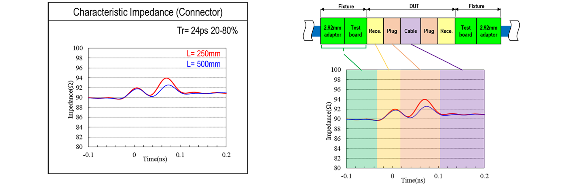
| TDR (Time Domain Reflectometry) |
Identifies the location and magnitude of characteristic impedance discontinuities in the time domain |
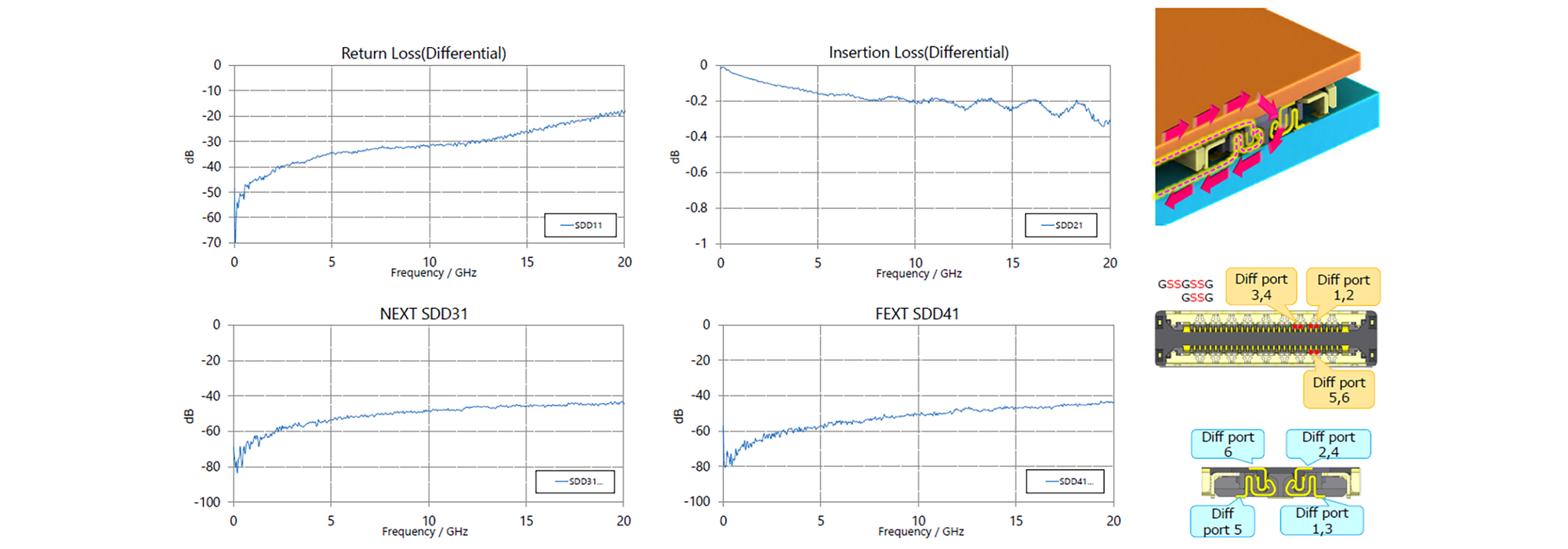
Measurement Example: NOVASTACK® 35-HDP
| Parameters | Description |
| Insertion Loss | Signal loss as the signal passes through the connector. This loss tends to increase with higher frequencies |
| NEXT, FEXT / Near-End and Far-End Crosstalk | Crosstalk between adjacent pins. Two types are measured: NEXT (near-end) and FEXT (far-end) |
| Eye Diagram | An evaluation of superimposed digital signals. Signal quality and transmission margin are evaluated based on the size and clarity of the eye opening. |
For connectors used in high-speed differential transmission, a key evaluation criterion is whether low-loss and low-crosstalk performance can be maintained across the required frequency range.
| Skew within a differential pair | In-pair skew refers to the timing difference between the positive and negative signal lines within a differential pair; it is caused by electrical length mismatches or uneven propagation delays. |
| Propagation Delay | The time it takes for a signal to travel from the driver to the receiver on a printed circuit board; this is the primary cause of timing errors and data transmission errors in high-speed, high-density wiring. |
5. Importance of SI Test Boards in High-Speed Connector Testing
To accurately evaluate high-speed, high-density connectors, SI test boards require:
-
・Transmission lines with controlled characteristic impedance
・Selection of low-loss PCB materials
・Fixture design based on de-embedding
With a design optimized for high-speed differential transmission evaluation, I-PEX's SI Test Board enables:
-
・Acquisition of the connector's inherent SI characteristics with high reproducibility
・Objective performance comparisons with competing products
I-PEX offers a lineup of SI Test Boards tailored to the characteristics of each connector series.
Micro-Coaxial Connectors: CABLINE® Series

The CABLINE® series consists of connectors designed for transmitting high-speed differential signals—such as PCIe, USB4, and DisplayPort—via thin-wire coaxial cables.
Key Points
- ・Insertion loss: Evaluation of high-frequency loss in thin-wire coaxial harnesses
- ・Skew within differential pairs: Verification of propagation delay differences during high-speed differential transmission
The CABLINE® SI Test Board replicates a measurement environment that takes actual cable connection conditions into account, enabling SI evaluation that closely resembles the operating environment.
Board-to-Board (FPC) Connectors: NOVASTACK® Series
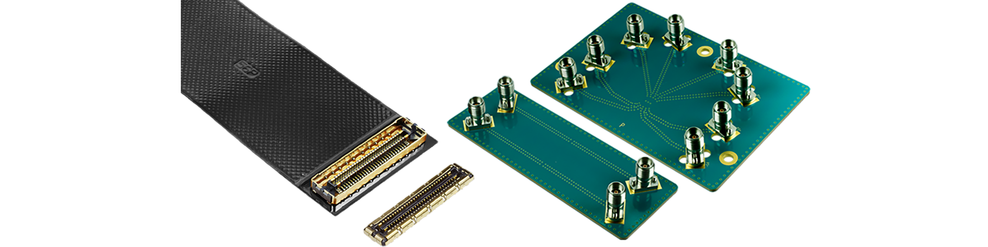
The NOVASTACK® Series consists of high-pin-count, high-density connectors used for board-to-board (FPC) connections. For SI testing of this series, it is important to conduct a comprehensive assessment that considers not only the connector itself but also the effects of wiring density.
Key Points
- ・Crosstalk (NEXT / FEXT): Evaluation of interference between adjacent opposing pins
- ・Insertion Loss: Evaluation of high-frequency loss during FPC connection
The NOVASTACK® SI Test Board enables SI testing under conditions close to the actual operating environment through a differential wiring design optimized for high-density wiring.
NOVASTACK® Series SI Test Board
FPC/FFC Connectors: EVAFLEX® Series

The EVAFLEX® Series consists of connectors designed for FPC/FFC applications and is widely used in devices that require moving parts or thin-profile mounting.
Key Points
- ・Understanding Characteristic Impedance Variations: Verifying the effects of FPC/FFC bending and wiring structures
- ・Insertion Loss: Evaluation of high-frequency loss during FPC/FFC connections
The EVAFLEX® SI Test Board enables SI testing under real-world usage conditions through a wiring design that takes FPC/FFC connection conditions into account.
RF Connectors: MHF® Series
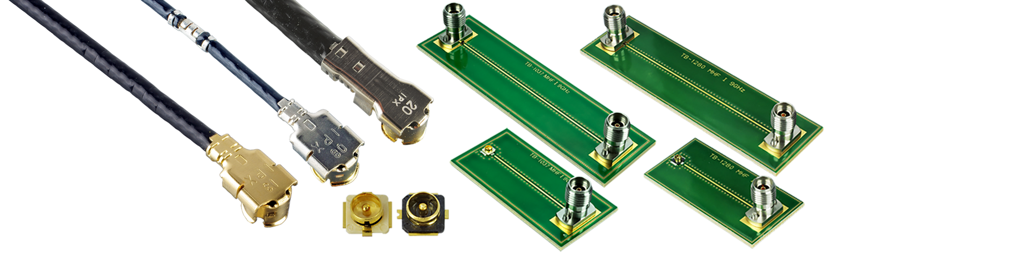
The MHF® Series consists of high-frequency coaxial (RF) connectors used for antenna connections and other applications, making evaluation focused on RF characteristics essential.
Key Points
- ・Return Loss/VSWR: Verification of characteristics within the operating band
The MHF® SI Test Board is designed specifically for high-frequency measurements, enabling performance evaluation suitable for RF applications.
As shown, using an SI Test Board optimized for the connector series under evaluation enables optimal high-speed transmission evaluation.
6. High-speed transmission connector testing must be considered in conjunction with the “evaluation environment”
To accurately evaluate the performance of high-speed transmission connectors, it is important to consider not only the performance of the connector itself but also the evaluation environment—including the SI test board and measurement methods—since evaluation results are increasingly influenced by the evaluation environment as data transmission speeds rise.
-At I-PEX, we provide comprehensive evaluation solutions that include not only connector design but also SI test boards and measurement expertise. Please feel free to contact us if you have any evaluation-related concerns.


